


rob82
-
Posts
1,383 -
Joined
-
Last visited
-
Feedback
0%
Content Type
Profiles
Forums
Events
Gallery
Media Demo
Store
Posts posted by rob82
-
-
Thread Re-birth 21/4/2013 and still no official fix?
Car R32 GTR 1994 JULY build...
Mine only happens maybe once every 200-500km or 3-6 days Very random and unpredictable. It happens rarely which is why I have not been so keen finding this problem specially when I see so many people having it and not one person finding an official solution.
Guys my aim is to one day fix this issue, whether it be changing to a D-metro or a whole new computer all together. Is there anything which is better then the PFC for the GTR other then the D-metro?
I am slowly changing every nut and bolt in this beast But ofcourse my aim is to get rid of the bugs 1st if possible. Car is not stock , -5s , Cams, AFM, Injectors, Fuel P, Coil pack-SF's, Gearbox etc... All internals are still stock and I am running at a Safe/healthy 330awkw.
I really want to get to the bottom of this now.... Im in sydney is there anyone wanting to chat about this seriously?
D-metro is the most manicured ecu of the PFC line up...
Where does the missfire occur? What plug gap? How old are the O2 sensors?
-
As has been said, you should only run one MAC valve(running two relies on the valves flowing and responding electrically the same) - unless of course your ECM is capable of twin boost control (sm4) and you can monitor exh back pressure side to side and balance the turbos that way...
As for your questions
1. The minimum requested on time of the valve should not be less than the valve dead time, if fact I would stay a whole factor of 10 away from that. It's really irrelevant but start with around 20hz. What is of more importance when running a closed loop boost control is the feedback frequency. Depending upon you ecu's capability 30hz is a nice feedback rate.
2. What you really need to sort out is what the minimum boost your willing to run vs the maximum boost. For a single sided actuator I would not recommend running over twice the gate pressure unless you have a very competent boost controller. So if you want to run 30psi on high boost then the minimum act pressure I would run is 15psi to have the best of both worlds...
3. Everyone is going to have a different number here as it will depend on the car.
4. Yes rubber mount where possible they can vibrate a bit.
-
If you're getting black smoke from det. would you be able to hear it?
Sorry to be so vague but generally if you can see puffs of black smoke you could be experiencing fairly heavy knock - so if you've got a good set of ears you may pick it up.
I believe what you are seeing is raw hydrocarbons(un/semi burnt fuel) exiting the chamber - which sounds weird as you've just thermally and physically shocked the chamber which you would think would give you a really good burn however most detonation occurs at the outer edges of the chamber where you may have a localized explosion rather than a progressive flame propagation from the spark plug... This may also be the reason that EGT's drop during det...
-
Black smoke = rich tune, Blue/white smoke = oil burning. What AFR it is running at WOT?
Not always - you often will see black smoke during detonation...
-
I am using a Blitz DSBC to control the MAC valve. It is a two position switch, just like the 3 port valves, but the pressure in the two hoses self bleeds when switched off, meaning I can control the upper and lower ports directly without the hose or gate holding pressure.
It seems it would hold massive boost as it presses down on the wastegate, (helping the spring) until it switches to the lower port, bleeding off the pressure from the top chamber and pressurising the bottom to open the gate. It just seems smarter to me than the way Turbosmart recommend using 3 or 4 port valves.
http://www.turbosmart.com.au/wp-content/uploads/2012/06/TS-0506-1001_Hypergate45_MAY_12_rev-2.pdf
I actually ditched this setup for a while as I decided to run 26psi of spring in the gate for safety. (I had a wastegate line pop off, the car ran over 3 bar for a week, causing the head to lift) The 3 springs softened over a few months though, and boost dropped to 1.3 bar so out with the 5 port again. I am now back to 2.1 bar after a tune.
Boost holds rock solid, but it still over boosts when I hit the soft limiter (when the auto decides it doesn't want to shift.) Much better response with the MAC setup too.
Not sure I really understand what the advantage is over a 3port - you may have to draw me a schematic.. If you connect port 3 of the Mac valve to the bottom side of the actuator and port 1 to the top of the actuator, when the solenoid is un energized port 1 is deadheaded, when energized port 3 is deadheaded, there's no path for the system to bleed off other than back to manifold through port 2.
I've always toyed with the idea of having a small pressure vessel that picks up on boost pressure with a check valve to stop it bleeding back to the manifold and use that as my "pilot" supply to the Mac valve, this way you will have whatever boost pressure you run onto of the waste gate even when spooling....
-
Yeah, I have tried the Forge one, But ended up with boost spikes from the back pressure. I think I'm just out flowing the little housing.
Have you looked at exh back pressure pre turbine? That sounds like such a weird issue to get at low rpm. With a relatively small exh vs largish intake housing your more likely to see a linear increase in exh bp vs rpm. I've never come across the issue your experiencing in any turbo car. Slight over boosts are more likely due to poor electronic control, like PI integral windup... At the end of the day the difference between an internal waste gate vs external wastgeate when you are applying pressure either side of the valve is minimal if any...
The dual port actuator would work better with a 5 port MAC valve from my experience, but am I the only one using a 5 port? All the controllers I have seen use the 3 port valves.
Whaaaa 5 port.... Does that mean you are using two spools? One open one close? Can't really see that making much difference mechanically, sure makes me think about how the control system will work tho...
-
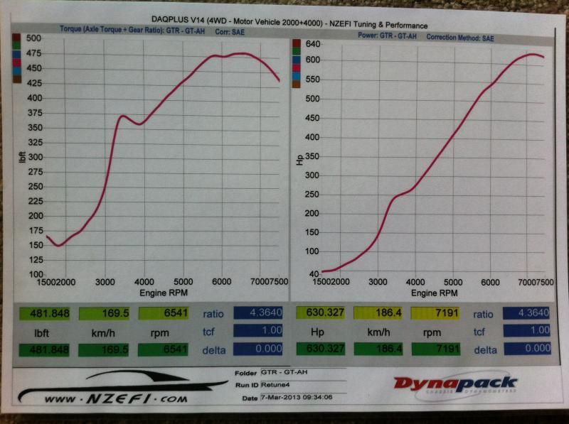
Hi Rob, the spike at 3400rpm that you see is the Wastegate struggling to stay closed, I am running the hard Wastegate spring, and even with the boost controller at 100% duty, the most we can get out of it is 20psi. The small exhaust housing is causing too much back pressure and blowing the Wastegate open too early.....hence the need to go to the larger external WG housing.
Don't get me wrong, the reponse is fantastic, and it really spools faster than the curve shows, and 630whp is nothing to scoff at, but it will be good to see what this engine/turbo combo will do with more breathing room and maybe some E85!
That sounds like a weird issue, have you though about a dual port actuator like this:
-
Any reason you didn't put more boost in the mid range to pickup the torque? Looks like a pretty damn good combo just needs a bit more midrange boost... I would try that before changing the housing...Here is the last dyno on it, it is only running the .92a/r internal wastegate housing which is choking it a bit, I'm waiting for a 1.05a/r external wastegate housing to become available to get the best out of this turbo.
As I mentioned before, The curve only tells half the story on response for this turbo, It just seems to spool from idle!

I like internal waste gates as the usually extract air from the turbine at a power friendly angle. No reason they can't be controlled as well as an external gate with the actuator and tuning..
-
Not really. "98 done right" and "e85 done right" have a reasonably standard % difference between them - given that one of the major variables (that of it being burnt in an RB25) remains the same. You have to assume that there are no other limiting factors involved, or you have to describe absolutely everything about both engines. The former is definitely the easier.
That's fairly true from what I've seen.
Would you also believe that e85 is likely to put less strain on the ignition system than 98oct.
-
It doesn't just want to be a check valve. What it wants to be is a check valve with some pre-load. You install it in the direction you want it to flow, but it takes a little pressure to crack it open. That stops it dripping/draining. You can get them from agricultural sprayer suppliers.
In fact, this has all been thought of about, um, 12+ years ago. Look up the Autospeed articles written by Julian Edgar when he built a controller system for IC water sprays, and you will find specific instructions one what sort of gear to use. If you're interested, the controller that he helped develop is still the only one that actually makes sense and works properly, even after all these years and even with the speccy ECUs available these days.
That's a big call - what make it so fancy?
-
Did you have a look at the new walbro 460lph. The specs I've seen says it will flow 5.6l/min @5bar and 13.5v compared to that of the 044 that flows 4.16l/hr @5bar and 13.5v it looks as though it would be great for e85. Can't see why this pump wouldn't be good enough for 500rwkw on pump or 350rwkw on e85.
-
Yes it is possible for a weak coil not to misfire but produce less power.
Usually the discharge time increases on faulty coils. Normal inductive coil discharge time can be anywhere from 10-50us, I've personally seen twice the dicharge time in comparing a good coil vs bad, can't remember the discharge time but it was a ba coil. If you look at an engine at 6000rpm with a coil discharge time of 50us and a bad coil at 100us that means if you are knock limited on the good coil cylinder than you will be 0.05/10x 360 = 1.8degrees retarded on that cylinder.
I meant to say "1.8degrees retarded on the other cylinders".
If the engine is not knock limited than generally you can get around the dodgy coils by advancing the timing past MBT to account for the slower coil discharge rate/coil voltage rise time.
-
Powerloss attributable to misfire aside, how much less are we talking e.g 1 cylinder @1.8 degree retarded as per the example above?
Could it reach as high as say 20rwkw loss with everything appearing to be 'normal'?
Well it depends, if you have 1 good coil with 5 bad you could have real problems. Also where your peak power occurs will affect power loss. The higher the rev range the more retarded the ignition event becomes which means the greater the power loss becomes. Using the same figures as before at 7500rpm the ignition retard will be about 2.25deg.
Dropping 2degrees on a knock limited rb25 could reduce power by 10-20rwkw quiet easily.
You can test the coils response by scoping the coil high voltage side, kind of need to know what your looking at though.
-
That is kind of what I meant actually. IE you could audibly hear that they are not up to the job?
So with the graph in the OP, the "low power" condition with the cheap coils weren't clean power runs, those cheap coils actually had misfire? What I'm getting at is whether or not it's possible for coilpacks to sound totally normal even at full noise (no misfire sounds) and just produce less power?
Yes it is possible for a weak coil not to misfire but produce less power.
Usually the discharge time increases on faulty coils. Normal inductive coil discharge time can be anywhere from 10-50us, I've personally seen twice the dicharge time in comparing a good coil vs bad, can't remember the discharge time but it was a ba coil. If you look at an engine at 6000rpm with a coil discharge time of 50us and a bad coil at 100us that means if you are knock limited on the good coil cylinder than you will be 0.05/10x 360 = 1.8degrees retarded on that cylinder.
-
Do they have closed loop narrowband/wideband control? Individual cylinder trims? Variable ignition attack/decel rates? Delta idle ignition control? Im also guessing they only have 4 saturated injector outputs - considering your running wastedspark on a 6cyl? Variable cam control?What's the trigger filtering like when using inductive style triggers?
I'm scepticle they will completely solve your ignition issues with just a change of trigger disk on those few cars that do have issues...
-
cost isnt an issue no girl friend lol
all jokes aside the results ive seen from v cams were not that great stroker motor was a better option
The narrower the cam profile the better the cylinder trapping efficency will be. This will also lead to greater gains when swinging the cams around. If you go Vcam - only go the step1 and keep the exh side std/ small as well.
-
Ah, yes i seen that function, would be great for cars without idle solenoid.
After some fiddling with settings, i got mine running well using the stock solenoid.
Its great for cars with idle control valves also. You will find that most manufactures run both an idle control valve and delta ignition control. Engine speed responds alot faster to a change ignition request than a change in idle air flow....
PM sent..
-
Running autronic sm4.
Just wondering why some rb motors are 15degrees and some 20?
If you running an SM4 you can run delta ignition control. It also has an rpm rate varaible so that you can apply positive or negative ignition changes based on the direction of rpm change - not just under or overspeed rpm event. Great ECU btw - my favorite. Who's pushing the buttons?
-
Just did a full build on a RAs the inline 6 configuration has great 1st order and 2nd order harmonics, but inherently bad at 3rd order harmonics, having an effective dampener is extremely important. More relevant as we see RB's hitting over 6-7-8000RPM in their normal factory rev range!
I'm pretty sure mine is faulty, and have ordered a brand new standard balancer to see if the problem really is the dampener.
If I leave it as is it will:
1.keep throwing belts at high rpm
2.cause other damage to engine components such as the block(cracking from harmonic vibrations),
flywheel bolts maybe rattling loose,
and oil pump damage/failure.
I'll post here again once I have changed the dampener
Did you have an inductive crank sensor? If so you can measure the third order harmonics by watching how the peak to peak voltage changes at specific crank angles vs rpm.
It's hard to measure second order harmonics without adding a delta strain gauge to the crank journal and using high speed logging - nothing a cheap oscilloscope can't do.
It would nice to think this level of R&D was involved during the product verification process.
-
Main throttle should be 0% open at idle and pretty much all idle air flowing through IAC/AAC valve. So Q45 throttle shouldn't matter so long as it is set up properly. ECU will still want to see the TPS at the correct voltage for idle (about 0.45V) otherwise all sorts of things go wrong.
Are you sure the Freddy is straight? Leak at the flange gasket would not be surprising (seeing as most people assume that they will leak there, based on the thousands that have). I know you did smoke test, but just double checking.
The throttle should be open enough so that the iac is doing very little at a hot idle, not all the work.
It sounds like you have an injector leak - did you use any oil on the injector seals when you put them back in?
-
I set them to 10degrees and run delta ignition control.
-
If you have too many teeth won't some ecu's lose resolution? As in too many teeth spinning past the sensor and it can lose track of their position?
If you miss a tooth your your in a world of hurt as your ignition event will then be (360/total number of teeth) out. The issues I've seen with too many teeth is when there is a bit of crank/cam flex which causes the triggering edge of the cam sensor to move past the triggering edge of the crank sensor. Have seen this issue on motronic 60-2 triggers where your cam triggering event only has a 6degree window.
-
Yes interesting idea thanks for that pic . For those of us that haven't had much to do with RB crank pulleys is that a modified RB25 one and do you have any pics of the back of it ?
I'm all for simple mods particularly to std components and if the notches don't damage the belt that's probably as simple as it gets to be .
The thing I'd like to know is does having more notches make the tuning results any better . I've read about toothed wheels having different numbers of teeth based around dividing into 360 ie 36 30 24 for 10 12 and 15 crank degrees .
Someone thats really into the electronic side would know if its necessary (for some computers) to have the tooth/notch count divisible by the number of cylinders as well .
Compared with rocking up to Nissan and being bitten $1300 for a new CAS this is lookng really good IMO .
Cheers A .
More teeth gives you a better ability to resolve smaller crank angles so in reality you should gain accuracy of the estimated crank angle. However it is dependent upon software and how the crank angle is calculated.
-
Personally I would rather try to use a new factory crank pulley damper and try to mount the toorhed wheel on the back of that . If one could be supplied set up and with a suitable Hall sensor and mounting bracket the install becomes straightforward .
With the missing tooth wheels I think these are intended to be used with ignition only computers or with basic batch fire fuel injection . To run sequential EFI you need a reference signal driven off a camshaft (in the RBs case) because the complete four stroke cycle takes two crank revs and only one camshaft revolution . The computer needs to know slightly ahead of time when the crank (no 1 cylinder) is approaching top dead centre on the beginning of the first revolution of the two rev cycle .
Somewhere there is a pic of the I assume exhaust cams nose with a wing on it for the hall sensor .
If as mentioned above a sensor can be mounted under the belt cover that would be good too .
If you could keep the standard CAS in position you would have a back up system or at least something workable while the crank trigger was being set up and tested . Looks standard though the average leg of ham probably wouldn't notice changes anyway .
Cheers A .
Missing tooth wheels are used on both sequential and batched fired ecu's. I believe the missing tooth wheels came about so that manufactures could still time an engine and keep it running if the sync sensor failed. It can also be used as an early way of determining where the crank is at before the sync is picked up.
65Mm Pistons - Ie Stock Bore For An New Rb26 Block
in Forced Induction Performance
Posted
Have you looked at total seal rings? I haven't used them myself but by design they look good. I would like to know if they are used in heavily boosted applications or just your run of the mill chevy's - which seems to be their market...