

mosquitocoils
-
Posts
1,695 -
Joined
-
Last visited
-
Days Won
5 -
Feedback
100%
Content Type
Profiles
Forums
Events
Gallery
Media Demo
Store
Everything posted by mosquitocoils
-
I'm baaack: C34 Stagea
mosquitocoils replied to mosquitocoils's topic in Projects, Overhauls and Build-ups
It's been a while, I've got plenty done which I'll post up in separate posts and try to keep in order. I managed to get the Stagea on the dyno but had some issues pop up. Firstly my fuel pump wasn't keeping up, we suspected from low voltage. Re-wired my new fuel pump straight to the battery using a relay and some 8AWG cable all the way from the front of the car back to the fuel pump. It looks a little messy here but this was just testing/finding the right connections. Everything was soldered and wrapped up, and the relay was tucked up in the side wall of the cargo area. Soldered in an in-line fuse as well, needed to pick up a 100w soldering iron due to the thickness of the wire. Voltage at the fuel pump was 11.2v at idle before running the new cables, then jumped up to 13.5v at idle after connecting this direct power feed up. Haven't tested the effect this has on fuel pressure or AFR yet but I'm hoping to get some of that data when I get back on the dyno. More info in the video here (if allowed): -
Adam's Stagea Drift Car ... Wait What?
mosquitocoils replied to Run-It-Hard's topic in Projects, Overhauls and Build-ups
Oh man I love this thread. I only just found it and wish more of the picture links still worked, or the website he linked was still up. Definitely some big inspiration for my stagea! -
I'm baaack: C34 Stagea
mosquitocoils replied to mosquitocoils's topic in Projects, Overhauls and Build-ups
Walbro 460 fuel pump install time Firstly fuel pumps suck in these cars! The fuel pump in the Stagea is under the floor of the rear cargo area on the driver's side. Remove the access hatch and you'll see this. Remove the clamps/lines (remember which is which!) then undo the big nut on top. Carefully pull the tophat up taking care to not bend the fuel level float. Then, and this is the most annoying part, disconnect the fuel pump cage (dark orange above) from the cradle which sits on the floor of the tank (yellow below). There's a big clip on the bottom you have to release while sliding the cradle. This took me far longer than I want to admit... then the cradle has to come up by unclipping it from the tank. I could have left the cradle on the floor of the tank but it was full of crud so I decided to get it out to clean it. Here is everything out of the tank, including a whole bunch of decomposed black rubber stuff from in the tank. While I had this all out and since I had run my fuel level very low in preparation for doing this fuel pump install, I siphoned what was left of the fuel (along with almost all the rest of that black crap) out of the tank and replaced with fresh fuel from jerry cans. To fit the Walbro 460 I had to trim the pump cage slightly with some pliers, nothing too big though. Then I ziptied the pump in as the original cage can't clip together anymore. I realise I'll probably have to replace these and plan on doing it soon. Then I ran the new, supplied wiring loom along the same path as the original and soldered it onto the original top hat wiring. Later on, my tuner and I decided to pull it out and re-do the wiring loom by using crimp-solder connectors, just in case the solder by itself cracks in future it will still be crimped together. Overall this went well and the car started up immediately. I had to adjust the FPR slightly but after about 5 seconds I had a rock solid idle and AFRs were all good. -
I'm baaack: C34 Stagea
mosquitocoils replied to mosquitocoils's topic in Projects, Overhauls and Build-ups
Right! I'm glad you said that, I was wondering what I'd done wrong haha -
I'm baaack: C34 Stagea
mosquitocoils replied to mosquitocoils's topic in Projects, Overhauls and Build-ups
It's been a few weeks and I did in fact manage to get coilpacks done. The PRP kit is such high quality and comes with their shorter stalks so I can fit my valley cover if I ever want to again (which I likely will. The kit comes with genuine Hitachi coils, shorter stalks, replacement loom and the billet bracket as well as all bolts for fitting. It looks great once fitted... shame about my cam covers though haha The only issue I ran into was the eyelet on the new loom that's used to ground the coilpacks was the wrong size to fit where my stock ground bolts to... so I cut it off and spliced into the original ground, which I also reconnected to the same bolt. I added a spade connector so I can remove quickly and easily in future without having to also unbolt the ground wire from the back of the head (being a S2 RB25, having no igniter box etc). The finished product: Once that was all hooked up it fired up right away with no weird hesitations etc. I played with the dwell settings in the Haltech but using PRP's suggested settings made it run like crap... so I reverted to the stock dwell times and she's running mint. I'll leave that up to the tuner. -
I'm baaack: C34 Stagea
mosquitocoils replied to mosquitocoils's topic in Projects, Overhauls and Build-ups
In order to save a few bucks I decided to wire in a couple of things myself before dyno time which turned out to be pretty easy. I re-purposed the stock boost solenoid wiring to run the new Haltech boost solenoid and mounted it in the same place. Of course for right now I have the duty cycle turned down to 0 at all load points (so still running only wastegate pressure to drive to my tuner) but I did verify it worked by changing the DC and listening to the solenoid clicking away. Then... I committed sacrilege... I CUT THE MAF CONNECTOR OFF ...So that I could re-use two of the MAF wires for my new Intake Air Temp (IAT) sensor, following the below guide for my RB25 S2 (white wire with blue trace = ground; orange wire with black trace = signal). I terminated the remaining MAF wire (12v) and threw the connector plug in the bin where it belongs... (not really, it's sitting safely in my old MAF which is sitting in my spare parts pile) Since I'm using a Haltech Elite it was really easy to change the wiring in the software, I didn't need to re-pin anything at the ECU. I just had to "remove" the MAF input in the software then reassign that input to IAT sensor input and it seems to work perfectly I.E. about 18-20 degrees at night then shot up to 40-50 degrees instantly when I held a lighter near it and dropped down when I removed the heat source. Then I ran a long two core wire across the radiator support and down to my cold side intercooler piping where I drilled and tapped the corresponding hole for the sensor. Coilpacks and fuel pump should be in the next week... -
I'm baaack: C34 Stagea
mosquitocoils replied to mosquitocoils's topic in Projects, Overhauls and Build-ups
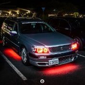
Managed to drive sedately just one suburb over to a local car meet and got some neat pics. Worked some more on my idle with the new injectors as well. I forgot I had slightly adjusted the main/base fueling table to get it running stoich at idle/cruising (with the new turbo but only standard injectors) and even though I looked over the table a bunch of times it didn't click. I adjusted those 9 or so cells related to idle and cruising and she sounds really good and sitting solidly on the rich side of stoich. It still swings lean on throttle tip-in (normal) but only for a second then drops down to the 12-13 range. Still not perfect and I'm keeping off boost/not pushing it hard, but I'm now more comfortable to drive it to my tuners shop now. Also got my base fuel pressure dialed in better by replacing the vacuum hose from inlet manifold to regular. I dunno wtf that blue hose I was using was (came with the car, looks like the kind you get in an ebay boost controller kit) but it was really flimsy thin (probably porous) "rubber" so I replaced it with some new typical black vacuum hose and also re-tightened the locking nut on top of the FPR and now it's dropping from 42-43psi down to just over 30psi which I think is about right. Sometimes it's the simple things! Anyway... pics - -
I'm baaack: C34 Stagea
mosquitocoils replied to mosquitocoils's topic in Projects, Overhauls and Build-ups
You're right, I will be adding a couple of sensors for engine protection. But for right now the gauge is enough to get my base pressure set and was only like $30 or something. The equivalent sensors to run to the ECU are $100-$250ea from what I've found so far, so will take a little more planning. I'm leaning towards getting my tuner to do them while he's doing everything else as I am leaving him a couple of small wiring jobs to finish off, mainly cause I don't feel comfortable hacking up the $700 Haltech harness myself hahaha. -
I'm baaack: C34 Stagea
mosquitocoils replied to mosquitocoils's topic in Projects, Overhauls and Build-ups
Fuel system time So my final parts pile consisted of: - Billet (BPP) top feed fuel rail - Bosch 1000cc injectors (+ loom adapters) - Turbosmart FPR800 - A bunch of fittings/adapters to make it all work The idea, at least for now, is to use the stock fuel lines and just adapt all these aftermarket bits to hook up to them. So even though the rail has a -8 size feed, I'm running stock 5/16 line up to the rail then using an adapter to go 5/16 -> -6 -> -8 into the rail haha. If I do go E85 then I'll need a new fuel filter as well and they generally have -6 inlet/outlets so my line setup would need to change then anyway. I set to work pulling all the old fuel lines off everything in the engine bay then pulling out the stock rail. The good thing about this forward facing style of manifold is that the rail was only 3 bolts and so I had it out in about a minute. Once everything was removed I put the new injector adapters into the manifold, popped the new injectors in and put the new rail on the top. I had the thought of also tucking the injector loom underneath the manifold and it makes a huge difference aesthetically, especially with the new loom adapters you can see sticking up between each runner. FPR getting set up with gauge Flex fuel sensor mounted down on the chassis/bottom of the strut tower I got to this point then realised the black paint on the manifold looked like crap... so what did I decide to do? Turned my simple single-afternoon-fuel-system-install into a week long process of stripping the paint off the manifold! I've never liked working with paint, thinners or anything of that nature... so my knowledge was limited but now I've got a good handle on things... and I think it came out really well considering I left it bolted in place! Now you can really see the different that tucking the loom underneath makes Rail back on The finished product I went into the Haltech and changed the settings to suit and basically fired right up! Ran great while cold... didn't like being started while hot though which is the opposite of what I assumed was going to happen! I'll keep working on figuring it out and also install my fuel pump soon. Then it's just R35 coilpack install and then off for a tune when money (and tuner's schedule) allows... getting excited! -
I recently did a manual swap on my Stagea - here is the guide I used for that and a lot of it is the same for the skyline. Of course any mention of 4WD doesn't relate to you. I also made a video of the process
-
I'm baaack: C34 Stagea
mosquitocoils replied to mosquitocoils's topic in Projects, Overhauls and Build-ups
Haltech flex fuel sensor is here... along with a Walbro 460 Also after speaking with my tuner I decided to get the PRP R35 coilpack kit... Hitachi coilpacks along with the PRP bracket, loom and their custom-made short stalks so I can tuck it away under the valley cover if I ever decide to do so... -
Hi guys, I recently did a manual conversion and made a video of the process... it's had a warm reception elsewhere, I'm hoping you find it useful as well. Not sure if linking my own video is allowed so please remove if not... This forum has been such a big help to me over the years so if I can give something back that's awesome
-
I'm baaack: C34 Stagea
mosquitocoils replied to mosquitocoils's topic in Projects, Overhauls and Build-ups
Headlights are looking good! Boost controller is here... just waiting to clear some bills before ordering the flex sensor, but should be here in time for tune in 2-3 months. -
I'm baaack: C34 Stagea
mosquitocoils replied to mosquitocoils's topic in Projects, Overhauls and Build-ups
While waiting my new boost controller and flex fuel sensor to arrive I thought I'd have a go at something I've had sitting on the shelf for a few months - halo headlights. Anyone can do this with pretty minimal tools and some patience (I'm still working on that last part). The longest part of this process was actually painting the housings... installing the halos was really simple. So if you're happy with the look of your headlight internals you could skip the painting altogether and save a day or so between waiting for coats to dry etc. To start, I removed all the external stuff from the headlight, any bolts and wires that can come off. As well as the couple of clips around the outside. Take out the bulbs to be safe. I preheated the oven to 180° - once at temp, placed the headlight in for 5-8 minutes (I tried 5 minutes the first time but it wasn't quite enough, so another couple of minutes helped). Once out, I laid it on a towel on a solid bench and (using an oven mitt) inserted a flathead screwdriver into a couple of spots to pry the two sections apart. It took some fiddling. I also used a (new) knife blade to help cut some of the butyl sealant in the tricky spots, although I purposely wanted to avoid doing this too much. It looks and feels like the edges may break but they take a lot of force before breaking... using a wider flathead lessened the chance of breaking. I had to keep working the flathead around, using extra flathead screwdrivers, trim tools etc to stick in places to prevent it from sealing back up. I was left with a pretty sorry looking headlight with semi-soft nuggets of butyl around the edges... now was a good time to try and smooth them along the edges a bit (if it's still soft enough). Inside is an extra fascia/housing which is held on with two screws so comes out easy. I chose to strip the paint off mine so I could black it out, although I left the actual headlight bulb housings alone so they remain the original chrome as I think that may be required by law. I soaked the plastic fascia in oven cleaner for about an hour (could be done in less but I got distracted)... it worked great! I came back and casually wiped the original paint off with no effort at all. Gave it a good wet sand to get everything off and scuff up the plastic underneath. Then some plastic primer coats Then I did a few coats of hi temp paint, though if I do this again I probably would use normal acrylic paint as the hi temp paint needs to be cured at many hundreds of degrees... far hotter than the plastic itself would let me heat it to. It started to melt/wilt slightly as I was trying to heat it enough to cure but I managed to get it out of the oven before any permanent damage was done. I didn't get any pics of the painted fascia alone, but here it is when I was just starting to fit the halos. I didn't bother sanding anything as these will be pretty hidden inside the headlight housings and it looked decent anyway. Now on to the halos themselves! I measured the ring sizes and found some 90mm LED rings on Amazon for the inner holes (surrounding the foglights) and some 150mm LED rings for the outer holes (surrounding the headlight bulb). I picked these as they were the cheapest 150mm rings I could find, just I could test proof-of-concept. This part required waiting around two weeks for shipping... I drilled some tiny holes around the edges and fed some fine jewellery wire through to wrap around the rings and tied it tightly at the back. I thought it seemed a bit ghetto but apparently this is how it's done... There isn't enough room to do the same on the outer/larger ring, but there is a perfect gap behind the fascia so I installed the LED ring directly to the headlight housing. Same deal - a couple of small holes and some wire to hold it in place. With the rings all ready and the electrical wires poking out the back near the bulb connectors, it was time to seal them up. I gave everything a good clean on the inside before doing so. I put the glass side of the headlight in the oven at 180° for 8 minutes by itself (until the butyl started running slightly), then the housing side into the oven for 3 minutes. Then I basically mashed them together and used a flathead to pick up any extra bits of butyl that squeezed out, trying to run it along the seam to help in sealing. And that's everything done! I'm really happy with how they turned out! It'll be interesting to see how long the LEDs last. I'm stoked I learnt how it all works and next time I'd be happy to step up to something higher quality but for now these look awesome haha -
I'm baaack: C34 Stagea
mosquitocoils replied to mosquitocoils's topic in Projects, Overhauls and Build-ups
Managed to get the Haltech wideband sensor hooked up. Got the CAN connector through the firewall grommet pretty easily... had to cut a small hole/slit in the grommet which took 75% of the time due to the way the ABS tower is mounted in front of it, not much room to work at all. Mounted the wideband controller in the engine bay and ran the new wideband O2 sensor across to the dump pipe. All up it only took 45 minutes, though the interior "install" still needs to be tidied up as you'll see from the pic The only thing I had to do other than plug the connectors together was the wire in 12v + ground. Luckily I had already worked out which wires these were in the Stagea's ECU loom from the previous attempt at wiring the Haltech in when I had the auto transmission. I still have all the pinout info printed out and sitting in the car as well haha. So I just had to look up which wire was switched 12v and piggyback off that, and same for ground. The software was foolproof to setup, just went in and enabled the wideband device (it already found it when I started the program, I basically just had to confirm it). Found out it's idling at about 12 AFR which explains the smell, also later figured out it was due to the Haltech base map containing very generic and very safe injector dead times. Once I found the values for stock RB25 injectors and plugged in values close to that (erring on the side of caution) I got the AFR up to about 13.7-14. My goal here is to gain an understanding of how each parameter of the tune affects each other, then move on to installing my 1000cc injectors, rail and FPR as that's introducing too many variables at once and if something isn't responding how I think it should, I won't know if I need to address software or hardware. -
I'm baaack: C34 Stagea
mosquitocoils replied to mosquitocoils's topic in Projects, Overhauls and Build-ups
Thanks man! The wideband is definitely high on the list of priorities... although today I managed to take it out for a test spin and realised my laptop's battery only lasts for 10 minutes now. So I'm tossing up between buying a new battery for it or just buying a new cheap-ish laptop just for tuning... yet another unforeseen expense haha -
I'm baaack: C34 Stagea
mosquitocoils replied to mosquitocoils's topic in Projects, Overhauls and Build-ups
Got the Haltech patch harness in the mail this week and hooked it all up, fired up the laptop and after a bit of fiddling managed to get it to start and idle on the Haltech's RB25 base map! It idles SO extremely smoothly too... I'm genuinely surprised haha. The car has never run this well since owning it, but I guess since I bought it it's had a modified intake pipe so was probably confusing the MAF, whereas the Haltech base map already runs off the onboard MAP sensor, win! Hopefully taking it out tomorrow for a few laps around town so I can start ironing out the bugs and dialing things in. The wideband also arrived but I haven't had a chance to hook it up yet... need to get a fat plug through the firewall on the passenger side, so I'm thinking of using the main loom grommet, but this will require me to drop the blower fan motor behind the gearbox to get enough space to push the wideband plug through. Shouldn't be difficult, just time consuming. -
I'm baaack: C34 Stagea
mosquitocoils replied to mosquitocoils's topic in Projects, Overhauls and Build-ups
Thanks man... at this point now I'm just playing the waiting game for paychecks as all I really need is the rest of the Haltech gear. Now that it's manual I've ordered the patch harness to suit R34 GT-T/WGNC34 so that should be here next week. That's going to make things very interesting as the MAF doesn't like the new turbo (idles perfectly smooth with MAF unplugged), so I'm hoping I can finally set it up to run mafless on the Haltech, and get it running at least solidly enough to use a daily driver for a few weeks while I sell my other car. From there it's a matter of ordering the wideband, the boost controller... and then eventually the flex sensor. I also just realised I still need to get a fuel pump as well, dammit! -
I'm baaack: C34 Stagea
mosquitocoils replied to mosquitocoils's topic in Projects, Overhauls and Build-ups
Hahaha man, I wish! With the big turbo on it at the moment, the stock ecu isn't enjoying all the extra airflow so I'm being pretty reserved when I do take it for test drives. Will have to wait until I have the Haltech sensors and hook them up etc before I can start playing around with the tune and make sure I'm not hurting the motor... THEN yes allllll the launches -
I'm baaack: C34 Stagea
mosquitocoils replied to mosquitocoils's topic in Projects, Overhauls and Build-ups
Manual conversion time! A few mates and I hired out a workshop for the weekend and smashed out 10 projects in 48 hours... and my Stagea's manual conversion was one of them. I'm not going to do a full write-up as there is already a great guide on this site but I will just quickly go through the process and comment on things I found useful along the way. I took heaps of pics of things that the guide didn't cover so will throw them in too, hopefully this helps someone out one day. Parts List: - Gearbox (RS4S AWD) - Clutch + pressure plate - Manual flysheet (freshly machined) - Manual spigot bush - Throwout bearing (if you wanted to do it while it's apart, but mine was already almost new) - Rear main seal (again, only if you wanted to do it while it's easy to get to) - Brake pedal - Clutch pedal and master cylinder - Clutch slave cylinder - Clutch lines + dampener loop - Shifter - Starter loom from the manual car (didn't use as-is but needed to use some of the electrical connectors and ran new wires) - Shifter + square-circle bracket for the surround - Handbrake + mounting bracket - Interior centre console - 4L gearbox oil of your choice First things first - we got the car in the air (the hoist was such a big help) and removed the auto transmission in just over 3 hours. It's a pretty straightforward process, just unbolt everything you can see, leaving the crossmember til last. The starter motor and bellhousing bolts were probably the worst part as there's not much room. Rear main seal is still very fresh with less than 5000km on the motor build, glad I got to see that. The next morning we got stuck into the interior. The stock wide brake pedal, footbrake pedal and footrest had to come out which was probably the trickiest part of the whole job. Three of us alternated getting under the dash on our backsand had a go until we couldn't do any more. I removed the drivers seat early and left it out til the end of the weekend and it helped a lot. Dropping the steering column was very easy being only two bolts, and definitely helped reach the upper bolts holding the pedals to the firewall. There is some plastic air ducting in the way but it is easy to move gently to one side while you get your socket extension past it. Then it was time to drill holes in the firewall for the master cylinder... definitely the SCARIEST moment of the weekend! You can see here how the holes are already pre-templated from factory but are covered over with material. So we ripped some of the padding out and drilled the holes. I drilled pilot holes first to ensure I was centred, then went bigger. From memory the big one was around a 37mm hole saw. I didn't get many pics here but the master cylinder should just slide into your new holes... you may need to unbolt the brake booster to side it forwards in order to get some more room in the engine bay but it will all go together. Then it's time to cut your stagea even more... for the shifter. We cut a decent size "square" out of the top of the trans tunnel, basically leaving all 4x bolt holes intact. You can see how the cutout looks from under the car here and why it's important to not cut too far. Back underneath the car now and we had to pull the auto spigot bush out. We had the right tool for it and it made it a breeze, it just popped out. This is very important as the manual spigot bush is different in size and needs to be swapped at the same time as the gearbox. In this pic we also had the freshly-machined flywheel sitting loosely in place. You can also see the attesa line hanging free - remember this for later, you'll see why! Now is a good time to run the clutch lines down the firewall from master - slave cylinder etc including the dampener section (if you are keeping it - I did for the same of keeping everything OEM for now, then can go to braided lines later if I decide to). Anyway here's the new Exedy clutch going on. Yes we moved the plate after realising we left it hanging down haha. Didn't get any pics of putting the gearbox in but didn't need to do anything special to get it in. We did tilt the motor down at the back as much as we could to help align everything but that's about it. Once it was up in the air on the trans jack I drained and filled it with fresh fluid. Once the gearbox was in, we could verify our shifter hole was good! We also mounted the handbrake while we had the interior apart. The handbrake bracket itself come from the donor car and we pop-rivited it into my car with tonnes of huge rivets, it's pretty obvious where to place it but we also had photos of the donor car to use as reference. This is really important if anyone's looking for parts - make sure you get the mounting bracket (as the boring RS4 doesn't have one under the console). Shifter and handbrake mounted and looking pretty good. At this point we hooked up the clutch lines and spent the next 3 hours trying to bleed the system and get pressure, with very sore legs... Eventually we pulled the slave cylinder back off the gearbox and saw fluid seeping out of it but just sitting inside the boot where the clutch fork goes... so it wasn't actually a visible leak, the boot was just getting fuller and fuller... very odd. To fix this, we just pulled the cylinder apart as much as we could and sprayed it all out with brake cleaner. When we put it back together we had pressure and could bleed the system properly so must have cleared some crud out of the seal! I have noted to buy a new slave cylinder when I can. At this point we started the car and I could move it under it's own power in gear, how good! Although we forgot something with the 4WD system as the 4WD and ABS lights were on... We had plugged the attesa line into the back of the new manual gearbox, but we hadn't bled the system yet and it obviously lost the fluid that was in the line. After bleeding it (with engine running, open the bleeder nipple on the back of the gearbox with a ring spanner) once (just quickly), the 4WD lights went out. Now for the rest of the wiring. On the manual gearbox there are 3 plugs - the two together are - - Front - Reverse switch - I cut and ran two wires up to the engine bay and made my own "loom" - Rear - Neutral (don't need, leave unplugged) - will explain below The plug by itself is the speedo, we cut the original connector on the engine bay loom side and soldered in the new connector for the manual speedo which came with the new gearbox. I think from memory it's a 4x2 plug near the fuse box. In the front of the engine bay near the battery are these 4x connectors used for the auto. Jump the first one as shown (neutral safety switch - lets you start the car). The second plug (grey) needs the black and green wires connected to the reverse switch on the new manual gearbox in order to have working reverse lights + dash warning etc. I cut this grey connector off my auto transmission to use again in the engine bay, and ran two very long wires down to the gearbox to the plug that came with the new manual gearbox, and wrapped it all in convoluted cable to tuck down behind the fuse box etc. Then handbrake switch wiring. I cut and extended the footbrake wiring from under the dash, around to the centre console and down to the new handbrake switch. It's just one wire (black and red, up between the steering column and the stereo, sorry for potato quality photo) that needed extending. I tidied everything up once I had finished testing, the below pics just show how I figured it out haha. The plug isn't made to click into the handbrake switch connector but it fits snugly in there with no problems so I just pushed it in. The g sensor/g-force sensor needs to be moved as the manual centre console won't fit if it's left in place. I bent the bracket flat and used the original bolt hole to secure it near the shifter and out of the way of the cup holders. It clears the handbrake by a fair bit even though it looks close below. Put everything back together, adjust clutch pedal free play at the stopper... then time to party! The car drives so much differently now... it's hard to explain but now it feels like my R33 did as opposed to the fancy falcon wagon it felt like with the stock auto box! It used to almost stall after a gearshift due to maf reversion and now it just doesn't. It also sounds so much nicer going through the gears rather than hearing it flare and hang at the top of each gear hahaha. -
I'm baaack: C34 Stagea
mosquitocoils replied to mosquitocoils's topic in Projects, Overhauls and Build-ups
Got the exhaust welded up... when someone does it for a living, they make it look too easy. My mate came over and did it suuuper cheap for me which is awesome! Started by cutting some bends and straight pipe then tacking together: The turbo has a 5 bolt rear and came with a vband adapter... but it wasn't a standard size vband, so we cut it off and replaced with a standard 3 inch vband. Here's the finished custom dump made up: Next up, screamer pipe: We're going to cut the screamer a little higher so it doesn't hang so low and maybe add another little bend to throw it backwards more, but I'm happy for now. The car sounds amazing with the new turbo... VERY loud as it's a straight through exhaust from the turbo back. Next on the cards is a varex cannon to sit right at the back so I can avoid attention late at night or around the popo etc as it's definitely way too loud to be legal! The new loud turbo/exhaust setup has also really brought the dumb auto transmission to my attention... the way it shifts, hangs between gears etc is REALLY noticeable now... ugh, can't wait to be rid of it (in about a weeks time!) -
I'm baaack: C34 Stagea
mosquitocoils replied to mosquitocoils's topic in Projects, Overhauls and Build-ups
Picked up a S1 Dayz bar! Needs a repaint anyway so may as well swap to silver as well... -
I'm baaack: C34 Stagea
mosquitocoils replied to mosquitocoils's topic in Projects, Overhauls and Build-ups
Hopefully man haha I really just want to drive it so badly now and see how it feels. Just need some time/save some money for the exhaust, ugh. -
I'm baaack: C34 Stagea
mosquitocoils replied to mosquitocoils's topic in Projects, Overhauls and Build-ups
Over the holidays I managed to get the new turbo fitted! Here it is for test fitting... Hypergear ATR43, Havoc Fabrications manifold and Turbosmart Hypergate 45 (gen 4 due to space concerns as the gen 5 is slightly longer) This also lead me into my first foray with braided lines and AN fittings. A quick trip to a well known motorsports parts shop and $250 later we have some fittings and some lines... glad I don't have to pay that again haha. The turbo came fitted with a -4 oil feed welded into it so had to make up the corresponding line with fitting on the block. Decided to do water feed as well due to space constraints against the chassis. Picked up a new oil drain gasket too which was super handy! Here is the turbo ready to go in for the last time - Time to torque down the manifold in sequence - Put a -6 coolant fitting on the block going to the turbo and kept the OEM line that runs around the back of the motor - Top down view showing how close the turbo is and why I used 90 degree AN fittings - Turbosmart gate in place and plumbed up (just for spring pressure for now) - The final view before test starting, with intercooler piping put back together... luckily I had some spare bits and pieces to make it all fit, kinda... I primed the turbo (CAS disconnected) until oil came out of the oil feed line... then I cranked for another 30 seconds or so and she fired up on the 2nd crank after that! Sounds healthy and great... no major leaks but I did have to tighten my fittings a little haha. Next step is to get the exhaust fabricated to fit between the new v-band rear housing and the cat. Probably won't be welding it myself this time haha -
I'm baaack: C34 Stagea
mosquitocoils replied to mosquitocoils's topic in Projects, Overhauls and Build-ups
I picked up a manual conversion which includes EVERYTHING I need: - S2 RS4S gearbox with 160k km on it - Exedy HD clutch, very new looking - Flywheel - Master + slave cylinders + lines - Clutch pedal - Manual brake pedal - Brand new manual spigot bush - INTERIOR CENTRE CONSOLE TRIM - Handbrake assembly - Manual loom (which is apparently different to the auto one, it has an extra couple of wires coming out and going to the box I think) I also scored some S2 interior door trims (I like them as they're a smooth looking black, as opposed to my 80s-inspired checker pattern cloth ones) and finally a radiator shroud haha. Very excited about this package! Got to take the actual car for several drives before my mate pulled the motor and gearbox out to sell so I could verify the gearbox drives really well, clutch is great etc etc. He only wanted the shell of the Stagea for an LS swap - which in itself is going to be an awesome project!
