


r33skylinegtst
-
Posts
931 -
Joined
-
Last visited
-
Feedback
100%
Recent Profile Visitors
4,300 profile views

r33skylinegtst's Achievements
")


-
Sorry to dig up an older thread but I recently fixed my second one of these and thought it wouldn't hurt to upload some decent pics and give a detailed explanation should anyone find the need to fix theirs as well - especially seeings as all the pics in the thread don't seem to be working anymore. I've done two now, the one in my car which is still working fine over 4 years later, and recently another one for a friend. I'm not an auto electrician by any stretch, but hopefully this will help the average Joe like myself - I haven't skimped any detail in case this is your first time with a soldering iron. It's really not that hard! I believe this only applies to Series 2 GTS-T's, the ABS relay box on series 1's is different (and the relay part numbers themselves are different too, pull yours apart as per below before ordering new ones if you aren't sure!) though I can't confirm that for sure as I've never pulled one apart. Could apply to GTR's/Stagea's as well, worth a try! Before you start, you will need the following; - A soldering iron, mine is a Jaycar special and does the job just fine - Desolder Braid - can also be had from Jaycar, I used the 1.5mm GOOT stuff - Some solder to put in the new relays, again Jaycar - The new relays (duh!) The ones I pulled from both relay units were branded Matsushita CB1-P-12V, I found replacement Panasonic units from RS Components Australia online, their part number is 815-5094. the price for two was about $14 inc shipping. 1. Remove the ABS relay located in the top LHS of the engine bay, there are three electrical connectors to unplug. The unit is mounted on a little metal spade-type mounting plate and it should slide off that. There is an 8mm bolt holding the mounting plate on, so you can undo that if it doesn't want to slide off, doesn't make any difference. 2. Crack open the relay. The plastic is pretty brittle after 20 odd years, so it is liable to snap - don't stress too much as you can use a cable tie later if it comes to that. Ease a flat head under either side, once you get one it should leverage off from there. 3. Now the case is off, you should be able to slide the circuit board and relays out from the lower plastic casing (that all the plugs connect to). When you've done this, it should look like the below in three pieces, the upper plastic case, the lower plastic case (with plugs) and the circuit board with relays. 4. Usually only one of these relays fails, but it stands to reason if one has gone the other probably isn't far behind so good practice to do both. If you give the whole unit a shake you'll probably even hear something inside one of the relays rattling around, a sure-fire sign it's shot. If you inspect the new relays, you'll see they mount via 5 little prongs, so to remove the old ones you need to get the solder off those prongs that holds them to the circuit board. Note that on one side only the outer 4 prongs are soldered in, the middle one is not soldered. Place the soldering iron tip on the solder around the prong, the aim here is to get the old solder melted again so that the braid can be used to soak up the solder. Have the braid handy and feed it in, or put it under the tip of the iron between the solder, either works really. Just be careful not to contact the plastic circuit board too much, you don't want to melt it. The braid and relays will get hot if it contacts the iron for too long so be mindful of that. Do this for all 5 solder joints on one side, and all 4 on the other. Take your time, you need to remove as much as possible or it won't come apart and you risk breaking the circuit board when you try to remove the relays. 6. Once you're confident the solder is removed, you now need to separate the relays from the circuit board. They usually don't just pull off, so I found the best way to remove them was to use a bench vice. Very gently wind the vice in so there's just a small amount of pressure on the sides of the board holding it in place. Can't stress this enough, do not tighten, you just want it suspended, you don't want to snap it! Then using a metal punch and a hammer, very lightly tap the tip of each prong of the relays, working your way around each one and you should see them slowly slide of the circuit board. When you have a tiny bit of movement you should be able to pull them off by hand. 7. Now push your new relays onto the circuit board in place of your old ones. Make sure they're on snug and now it's time to bust out the soldering iron to solder them back in place. Put the iron on the prongs and give it a few seconds to bring some heat in, then try and melt the solder onto the prong (not the iron). You don't just want a blob on the prong, it needs to melt onto the circuit board as well or you won't have a good connection between the two. If you keep the iron on it for a few seconds you should see it dip and sink into the board. Don't be heavy handed with the solder here, you don't need to feed a lot of it in just enough to cover the prong and make that contact with the circuit board. Repeat for the 8 other prongs (9 total). 8. Now you can reassemble the unit to the casing. Slide the circuit board onto the bottom plastic casing part with the connectors on it. It will only fit one way so if it doesn't want to slide on, turn it round. Place the metal cube things on top and slide the top casing on. If you broke any tabs pulling it apart, you can use a zip tie to pull the casing closed. 9. Refit to your car, kick her over and marvel that the ABS light is now gone. If not, double check that your solder joints have been done correctly (I stupidly missed one the second time I did it, so it pays to slow it down and not rush the process). Hope this helps someone else out in the future Happy to answer any questions best I can if anyone gets stuck.
-
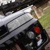
Hi there, Looking to purchase an OEM R33 Series 2 lower lip (not a fibreglass copy). I'm located in the ACT but don't mind paying freight costs etc if interstate. I've attached an image for reference. If needed, happy to purchase with the full front bar. Let me know if you can assist. Thanks in advance, Graham
-
-
-
Spotted a red R35 GTR in Queanbeyan a few days back. Was too busy gawping at it like an idiot to notice the driver wave.
-
 Sold pending payment
 -
Sorry mate, not on here often, sent you a reply
-
Bump - still for sale
-
Bump!
-
Yep, that's the one.
-
For sale is a V35 Skyline 'Navtool' - this is an interface box that allow you to connect external video sources to the factory dash screen. Through a shipping error I ended up with two of these, I've installed one in my parents vehicle - as pictured - and the second one is for sale. It connects behind the back of the factory GPS DVD drive (above the glove box), and gives two video inputs, whilst still retaining the factory info screens if you use them, and will switch to the factory reverse camera (where installed) when the car is put in reverse. These are a plug and play system, so no hacking of wiring looms etc. It should be noted that the factory screen is NTSC, so to connect say a DVD head deck you'll need the ability to switch video inputs from PAL to NTSC (most JVC's will do this for example). This may also fit the M35 Stagea as they appear to use the same screen, but I can't confirm that for sure. $200 firm including shipping Australia wide - these normally retail for around $300 by the time you pay postage from the states. PM me if interested.
-
Hi, Chasing the left hand and right hand front lower control arms to suit an R33 GST-T posted to Queanbeyan, NSW 2620. Not overly fussed with the condition of the ball joint as it will be replaced. Thanks, Graham
-
Search Issue
r33skylinegtst replied to *LOACH*'s topic in Site discussion - including Ideas/Feedback & Bugs
I'm also having this issue, using Internet explorer 9, nothing I type in the search box is returning any results. Haven't had any issues in the past either with the same browser. -
Hi, do you have the passenger side BOSE speaker? if so how much inc postage to Queanbeyan NSW 2620? Cheers
-
R33 Gtst - Creaking Steering When Hot
r33skylinegtst replied to r33skylinegtst's topic in Suspension, braking and tyres
Thanks for the reply! Got under it with some silicone spray and went over the usual suspects, noise is not nearly as bad but there is still a definite creaking there. It happens when partially turning the wheel, not necessarily on full lock. What else should I be looking for? -
R33 Gtst - Creaking Steering When Hot
r33skylinegtst posted a topic in Suspension, braking and tyres
Hi, I've started having an issue with my steering that's just been getting gradually worse. It started off as a small creaking noise when turning the wheel, but now it's gotten to that point that after a 30 minute drive the car sounds like a rusty gate creaking everytime I so much as think about turning the wheel, even when slowing down to stop it will creak. I've done the usual and checked fluids, i noticed my power steering lines were leaking so I replaced all of them, flushed the existing fluid out and topped up with new fluid to the correct level, bled the system etc, leak seems to be fixed but the creaking is still there. It sounds as if it's coming more from the LH wheel, but I can't narrow it down to anything specific. I have aftermarket lower control arms that are approx. 5 years old, but other than that every other component is stock original items. What else should I be looking for? Thanks for any suggestions in advance.

