

Announcements
-
Similar Content
-
-
Latest Posts
-
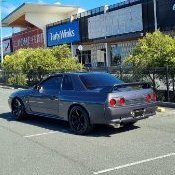
 If im following along correctly. You purchased a low k'm stock bnr32, fitted some wheels I will assume they are a square set of wheels and tyres eg same width and offset and tyre size front and rear, if they are square then you haven't change your handling from factory but have more grip. You fitted some coilovers and wound them lower now have more negative camber and a firmer ride with less body roll. Now if you want sway bars this will bring in the oversteer understeer choice. A larger stiffer rear swaybar by it's self will cause more oversteer, how much effect this will have will depend on your coilover spring rates, If you feel like your car understeers right now and you don't like it a aftermarket rear swaybar might be what you need. I would recommend fitting front and rear swaybars with adjustable ends to keep a more balanced setup and can be fine tuned by moving the end links in different holes.
 -
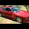
 @Duncan whats the easiest way to remove the flare?
 -
Cheers guys for ideas, gives me something to think about. @PranK my local track has one hairpin turn and also street sprints I want to do have hairpin turns so a few.
-

-

By alex.typex · Posted
Hello everyone. Greetings from Spain to everyone. I am from the Canary Islands. I have a r33 gtst M type. I am fully involved in the project. In networks they know me as alex.typex. Youtube XXGarage. And I'm in the middle of programming my Apexi power fc. A pleasure to be part of this great community. Greetings.
-


Recommended Posts
Create an account or sign in to comment
You need to be a member in order to leave a comment
Create an account
Sign up for a new account in our community. It's easy!
Register a new accountSign in
Already have an account? Sign in here.
Sign In Now