

stripey
-
Posts
156 -
Joined
-
Last visited
-
Feedback
0%
Content Type
Profiles
Forums
Events
Gallery
Media Demo
Store
Posts posted by stripey
-
-
if you have factory 17" wheels you can fit 06 350z non brembo twin piston calipers to it. Not as good as the r34gtt or 350z brembos. However it is an upgrade over standard giving you 320mm rotors and twin pistons and you can get the 06 350z rear caliper bracket for the rears allowing a slightly bigger rear rotor
-
On 24/10/2012 at 10:44 PM, PN-Mad said:
Yeah, can't imagine an off the shelf box controller. I know the ECU tells the gearbox line pressure commands, becuase I have the uprev that allows me to alter them, however that is just one map in what I imagine would be 5 or so different maps for various aspects of the gearbox.
I don't know what is stored in the ECU, and what is stored in the GB ECU. There is a hell of a lot more to it than just the line pressures.
off the shelf.. yes http://automatictransmission.com.au/shop/compushift-nissan-re5-automatic-transmission-controller/
but at half the price of my car i think not -
or theoretically. 07 350z NON brembo brakes will fit front and rear giving you a 320mm twin piston front and a 308mm single piston rear with the ability to run a 17" space saver spare wheel still
-
-
-
Found in service manual images below
-
 1
1
-
-
If you log in and "view photos" it wont show have to look in album. But yes it is there on further clicking and i still stand by the list i put up directly from service manual as for me its easier to read
-
1
-
-
2 hours ago, joshm35 said:
Search 'm35 tuners' on facebook and look in the photo gallery. Craig did a digram years ago that is floating around so there is one out there
yah i know there is an image / pfd. Its on page two of this thread just sometimes an actual list is easier. P.S. no images in said page on facebook
")
-
VQ25DET ECU PINOUT LIST
1 No.1cyl. Injector drive signal 2 No.2cyl. Injector drive signal 3 No.3cyl. Injector drive signal 4 5 No.1cyl. Ignition signal (Pawatora drive signal) 6 No.2cyl. Ignition signal (Pawatora drive signal) 7 No.3cyl. Ignition signal (Pawatora drive signal) 8 eVTC electromagnetic retarder control signal (left bank) 9 eVTC electromagnetic retarder control signal (right bank) 10 Canister purge control valve control signal 11 No.4cyl. Injector drive signal 12 No.5cyl. Injector drive signal 13 No.6cyl. Injector drive signal 14 15 No.4cyl. Ignition signal (Pawatora drive signal) 16 No.5cyl. Ignition signal (Pawatora drive signal) 17 No.6cyl. Ignition signal (Pawatora drive signal) 18 19 20 21 22 Fuel pump terminal voltage control output signal (FPCM) 23 24 25 26 Throttle motor relay control signal 27 Supercharging pressure control solenoid control signal 28 29 30 31 C / U power supply (the counter electromotive current feedback circuit) 32 Fuel pump relay control signal 33 Engine warning light 34 Engine rotation speed output signal (to HICAS C / U) 35 36 37 38 ECCS & IGN coil relay control signal 39 O2 sensor heater control signal 40 41 42 Key SW (START) signal 43 Key SW (IGN) signal 44 Neutral SW signal 45 46 47 48 C / U earth 49 50 Adaptive cruise control system SW signal (car with adaptive cruise control system) 51 52 53 54 A / T mode (Snow mode) SW signal 55 Stop lamp SW signal 56 57 C / U earth 58 Sensor ground 59 Brake SW signal (car with adaptive cruise control system) 60 61 62 Air flow meter signal 63 64 Accelerator sensor 2 Power 65 POS (position) sensor signal 66 PHASE (phase) sensor signal (right bank) 67 Battery power supply 68 69 70 Accelerator sensor 2 Ground 71 Knock sensor signal 72 73 Accelerator sensor 1 signal 74 Accelerator sensor 2 signal 75 PHASE (phase) sensor signal (right bank) 76 The intake air temperature sensor signal 77 78 79 80 Air flow meter earth 81 Refrigerant pressure sensor signal 82 Supercharging pressure sensor signal 83 Throttle sensor 1 signal 84 Throttle sensor 2 signal 85 86 PHASE (phase) sensor signal (left bank) 87 Oil temperature sensor signal 88 89 Power steering oil pressure sensor signal 90 91 O2 sensor signal 92 93 Water temperature sensor signal 94 95 PHASE (phase) sensor signal (left bank) 96 97 98 99 100 101 Throttle motor drive signal 1 (open signal) 102 Throttle motor power 103 Throttle motor drive signal 2 (close signal) 104 105 106 Injector earth 107 Throttle motor ground 108 Injector earth 109 CAN Communication line H 110 C/U power supply 111 Sensor supply 112 C/U power supply 113 CAN Communication line L 114 115 K line (data transmission and reception of C / U) -
On 23/01/2014 at 0:56 PM, scotty nm35 said:
They will lose brightness over time, but seriously, how many hours a day do you use them on average? They might last years longer, and at the price of OEM burners I would keep the old ones a little longer.
Should have told richzx to replace them lol. Now i'm in charge of replacement so they lasted a further 2 years and 9 months.
-
Would it be worth taking a bolt in to get matched and replace all of them. Or are they all different sizes?
-
Negative. And probably just needs new belts
-
http://infopart.org/nissan-39101al860-part
Says stagea 2001- 2007 for the number 39101AL860
-
39101AL860 left side front oem nissan number
39100AL860 right side front oem nissan number
-
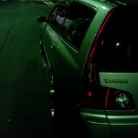
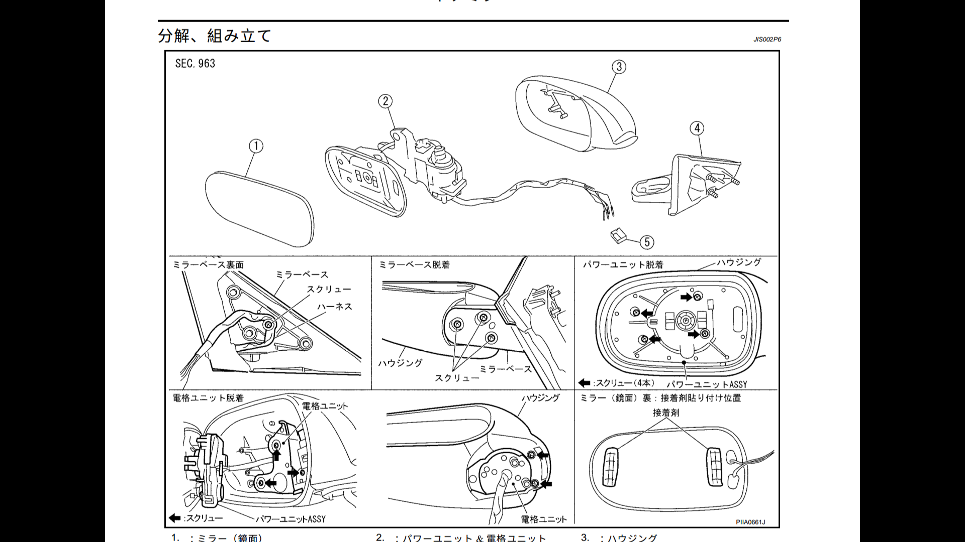
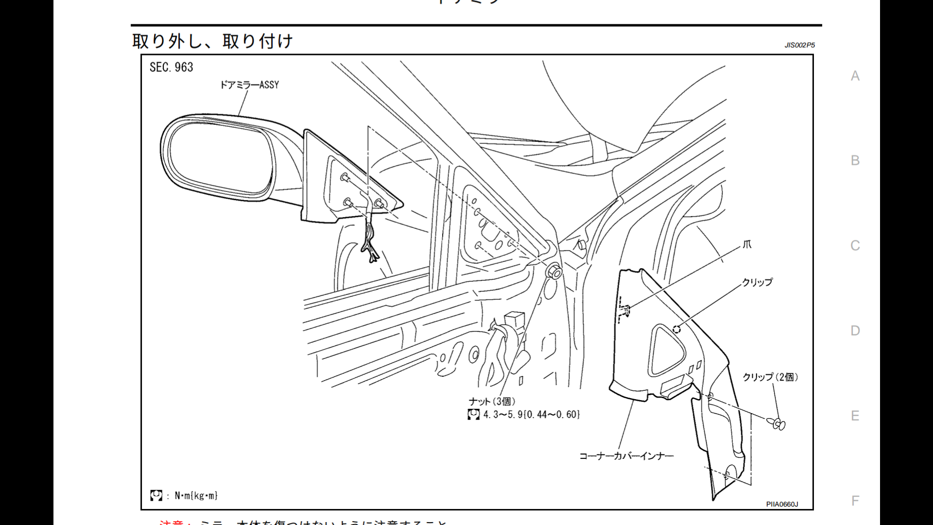
After reading a few threads and seeing the only real options we "had" for a broken front cv joint was a second hand replacement or a rebuild and I wasn't happy with that so i did some digging.
What i stumbled across was this image in the NM35 Stagea service manual.
With part numbers for the whole units Z80T70C ( Left side ) Z80T82F ( Right side )
so went back on google and typed in the numbers and i got a couple of hits
below is an image from a 2006 G35 sedan service manual
and the same numbers pop up Z80T70C and Z80T82F
here are some other links / vehicles with same part number
R34 skyline http://www.manualslib.com/manual/814884/Nissan-R34.html?page=224
R32 skyline http://nissan-skyline-r32.com/chassis/drive-shaft/168-drive-shaft-assembly-and-disassemblyand an ebay link to some New infiniti G35 axels http://www.ebay.com/itm/2-New-CV-Axles-Front-Left-Right-OE-Repl-With-Warranty-Fit-Infiniti-G25-G35-G37-/131641729761?fits=Make%3AInfiniti|Model%3AG35&hash=item1ea67562e1%3Ag%3AG9cAAOSwYHxWNNcI&vxp=mtr
please point out if i am missing something blatantly obvious
-
 1
1
-
-
just a question to this that may be in the know.
is there any reason why older threads images do not load?
is it a forum issue or a photobucket issue? as every thread 2015 and back every image will not load
and there are alot of informative threads that would make it easier to understand if the images were present.
jarrod
-
44 minutes ago, yuma said:
Finally got mine from compliance and got it regoed today. So damn happy with it. Gonna have to roll the rear fenders but.
350rx black with black leather.very nice indeed, north or south?
-
Did someone say dish?
-
2
-
-
This thread is all about highflows. Thats been well covered. Im simply asking is there a core replacement with a steel turbine
-
Are there options for me if i simply want to upgrade core to one with a steel turbine rather than ceramic ? I have not seen it pop up at all and it is an upgrade in terms of material used
-
Compression bush
-
Check either autobarn or supercheap with their online vehicle search function. Unfortunately i cant remember which one has them but it brings up a full list of bushes for our car front and rear
-
Superpro have all our bushes i believe
-
i prefer impul one
Takeros kit


Vq25det Trigger pattern
in Wagoneers
Posted · Edited by stripey
researched the crap out of the DET3 by ecu master and seems like a good product.
i didnt look into the EMU as i was just looking for something basic.
trigger is 12-2 12-2 12-2
some will say its a 10-2 10-2 10-2 trigger but it is not the case the way you look at the 36 tooth trigger wheel is to imagine all 36 teeth are in place and for ever 12 teeth you subtract 2 giving you the 12-2