


SSM
-
Posts
67 -
Joined
-
Last visited
-
Feedback
0%
Content Type
Profiles
Forums
Events
Gallery
Media Demo
Store
Posts posted by SSM
-
-
On 14.10.2017 at 6:03 AM, KiwiRS4T said:
Thanks
So use the rear turbo return as a crankcase vent is no good?
I'm a bit concerned to have a return from the catch can to the oilpan.
-
5 hours ago, djr81 said:
You want to get the blowby in the sump out of the engine without it having to go through the oil gallery. So if you can connect a line to the pan above the oil level then you can hook the other end into your catch can. Which is the age old fix for engines with oil carry over in the blowby.
Already got one on each side ?
-
Hello
I have now run my RB26 for two seasons. About 14.000km in total. I re did the hone and new piston rings this spring and buildt a new catch can. But it is coming some oil out from the filters on top of the can. I also had aboud 3dl of oil in it after 2500km drive on the Autobahn including 2 laps at the Nürburgring.
I have the rear head drain to under oil level. As I now understand this is wrong?
My setup is:
-Sock balanced bottom end.
-Jun oil pumo with spline drive gear
-Drilled oil return galleries to match head gasket
-Jun oilpan baffles
-Mines head baffles
-1.2mm restrictor
-AN10 from rear turbo drain to top of catch can
-AN10 from right side of oilpan above level to top of catch can
-AN10 rear head drain to under oil level in oilpan
-AN12 from rockercovers to top of catch can
What I'm thinking is to move the head drain to the position on the right side of oil pan above oil level. And only have the rear turbo drain as crank case to catch can ventilation. Is that a solution?
-
2 hours ago, R_34 said:
How much boost ?
Think we peaked at 1.35 bar
-
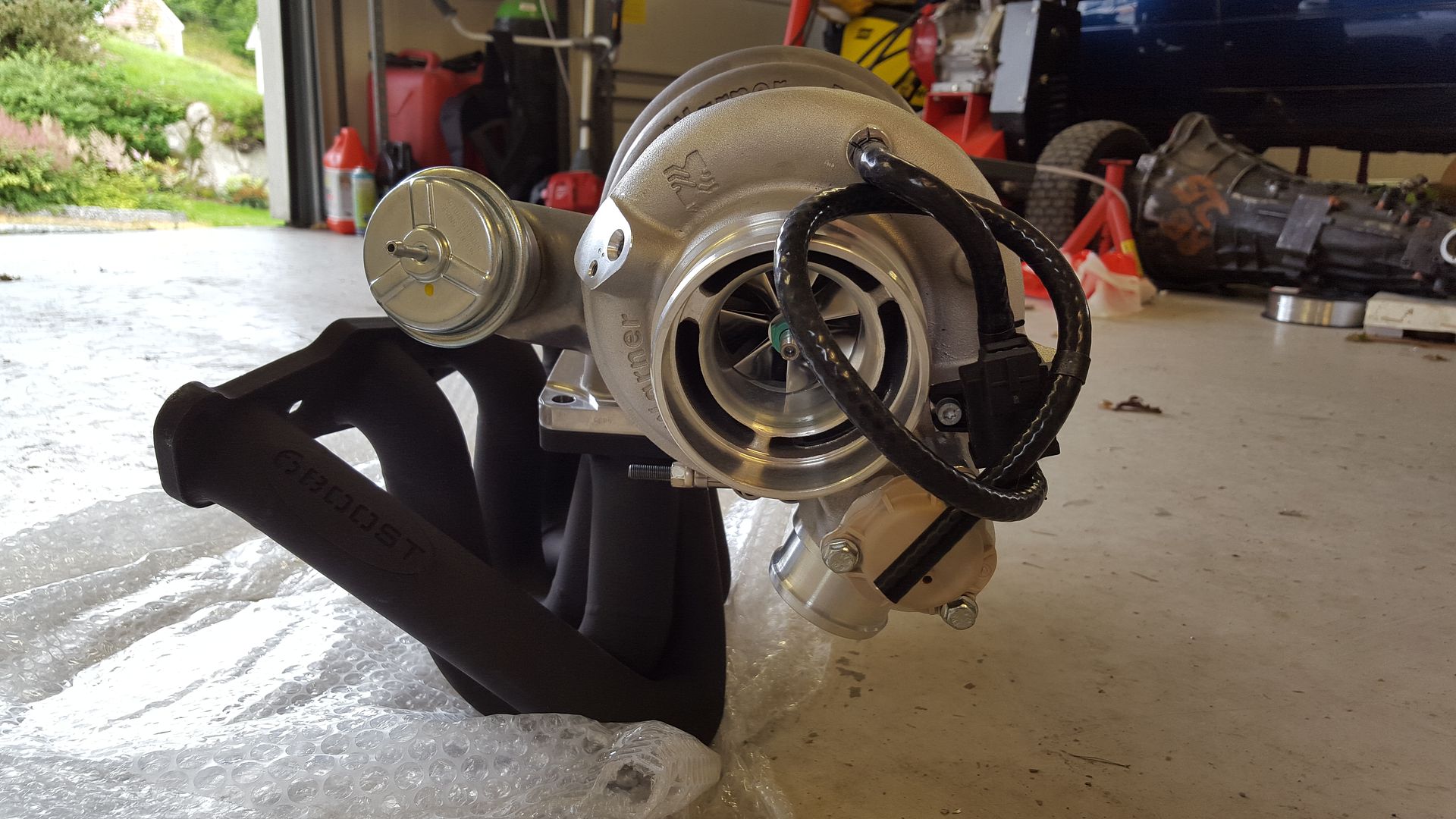
Here is my dynosheet with EFR 7064 T4 .92 internal wastegate.
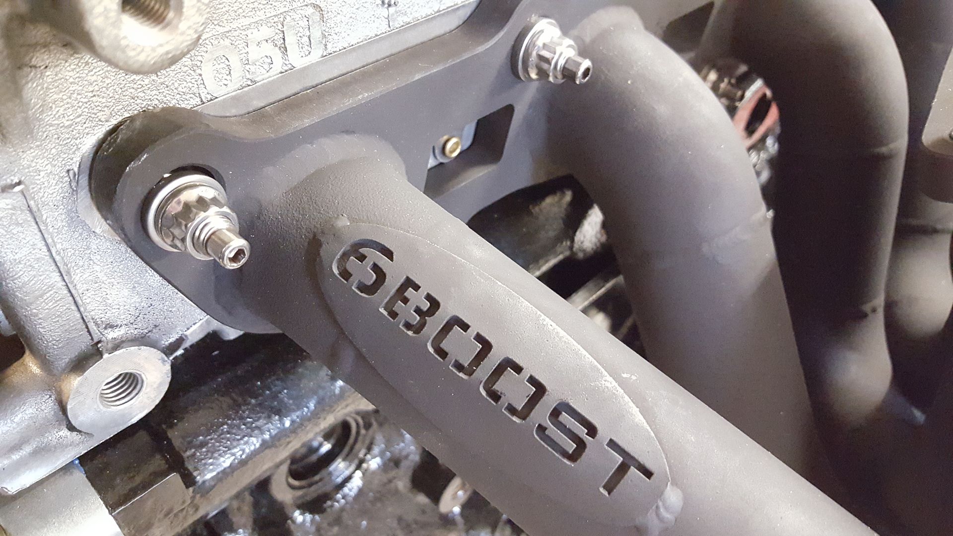
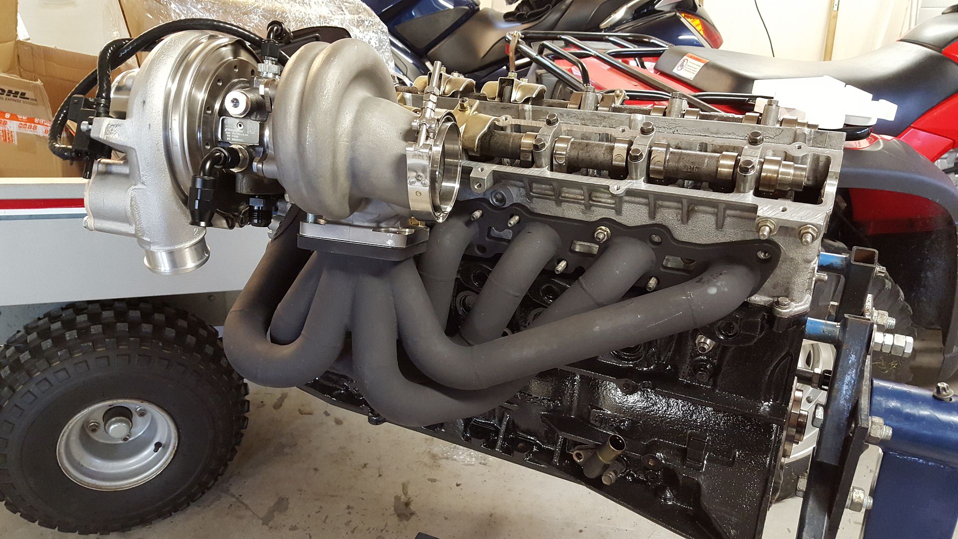
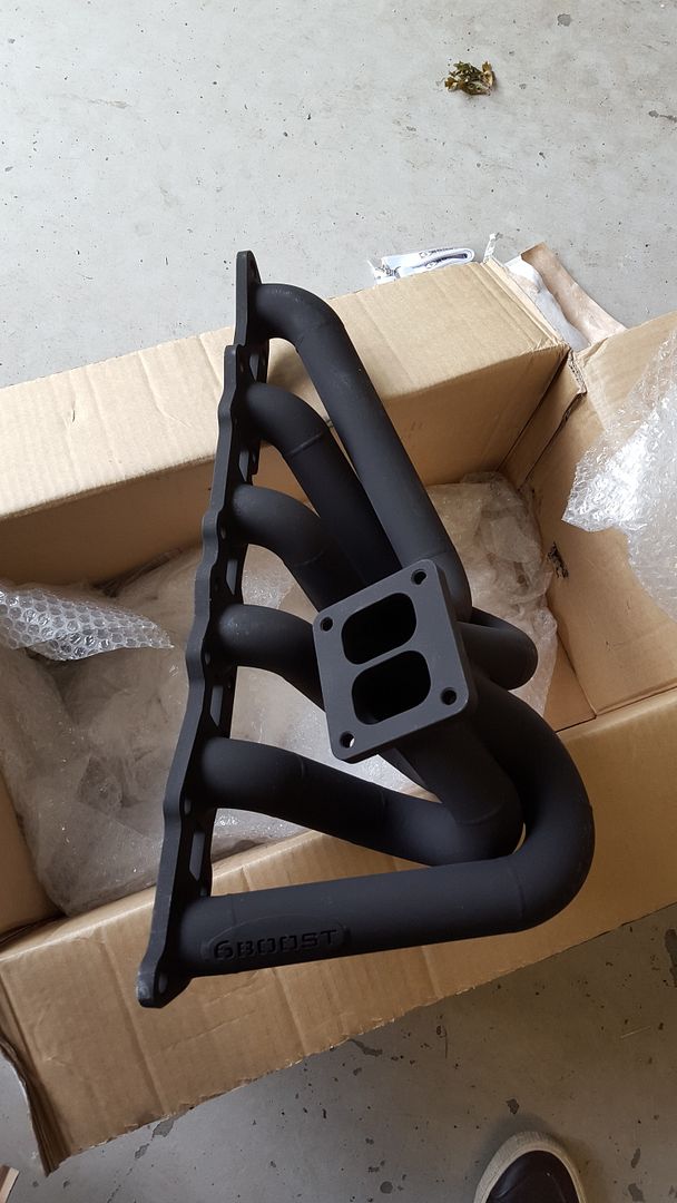
RB26 is stock, fully balanced. 6Boost manifold, 3" exhaust. Bosch Motorsport 970 injectors. Stock ITB setup.
You can see it dies out on top. So I will probably go for the 7670 T4 for 2017 season.
This is on 98 RON fuel. Measured on the hub.
-
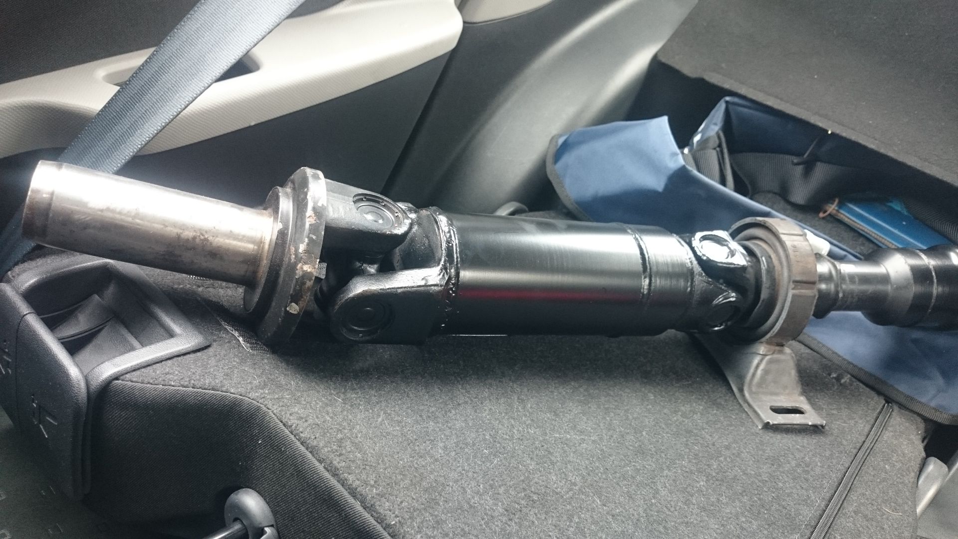
Using the RB25 gearbox, and it is leaking from the front and rear shaft. Car almost catch fire yesterday because of it.
It is now drivable and finished. Been testing yesterday and got some minor things to take care of.
Got some oil leaks that is nr1 priority.
-
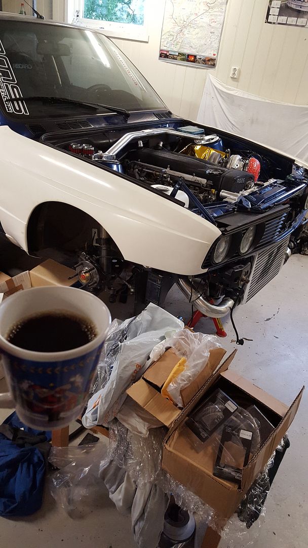
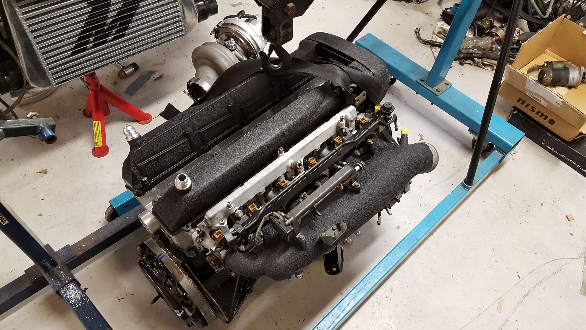
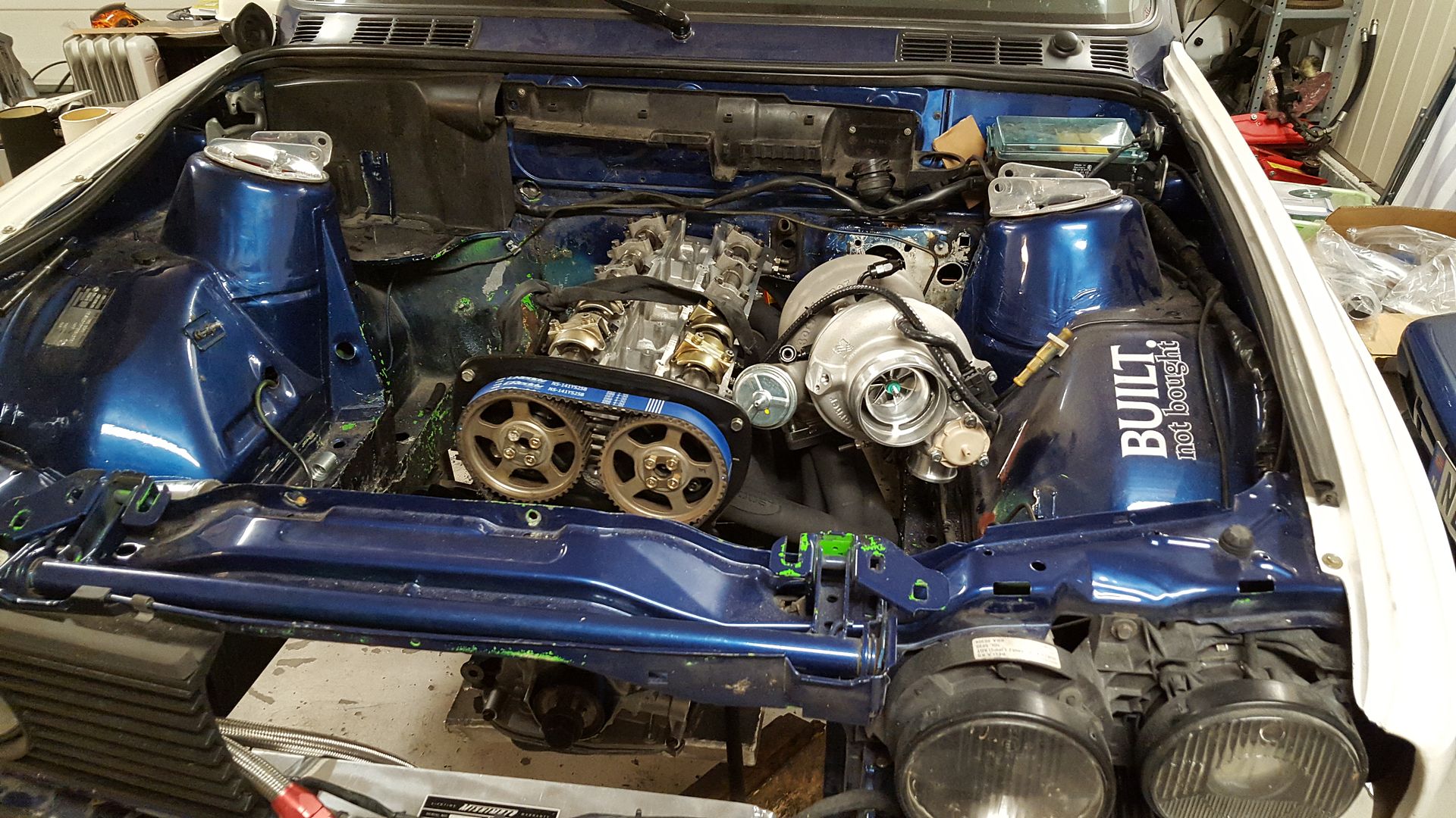
I got some things done with the car this weekend. Not that everything can be seen on photos. I removed the engine to put on the remaining parts in the oilpan. And sealed it for this time.
As usual, I start off with a coffee break!
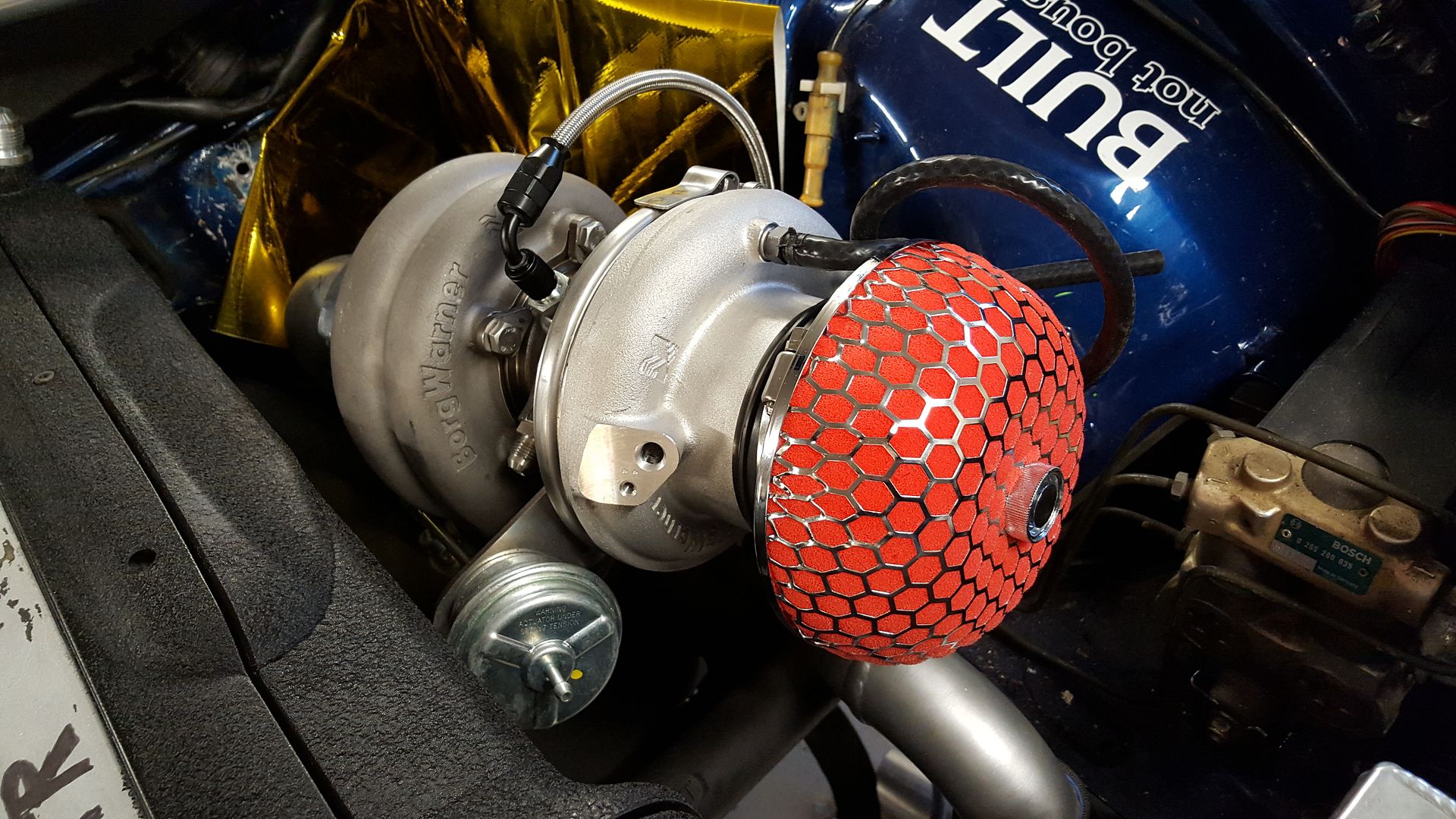
The air filter I will be using.
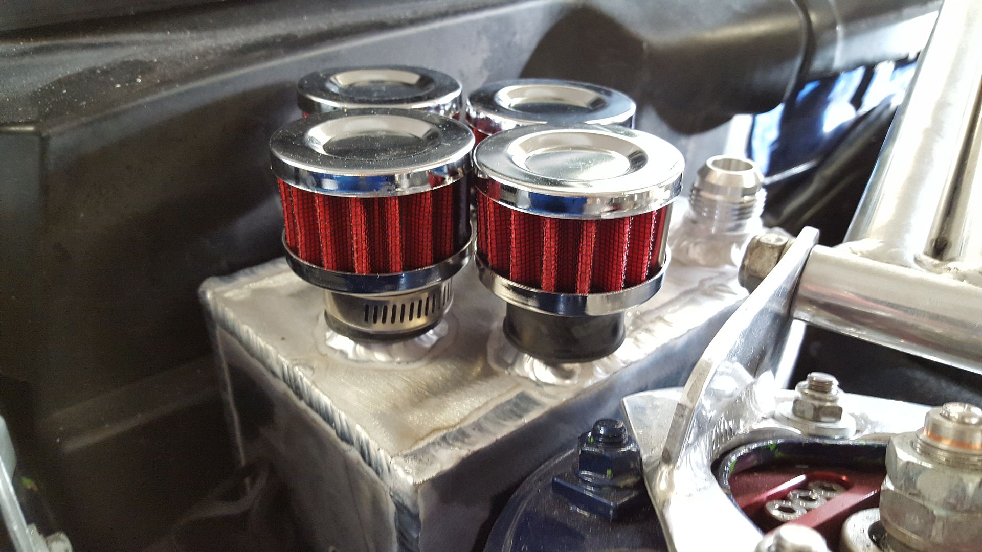
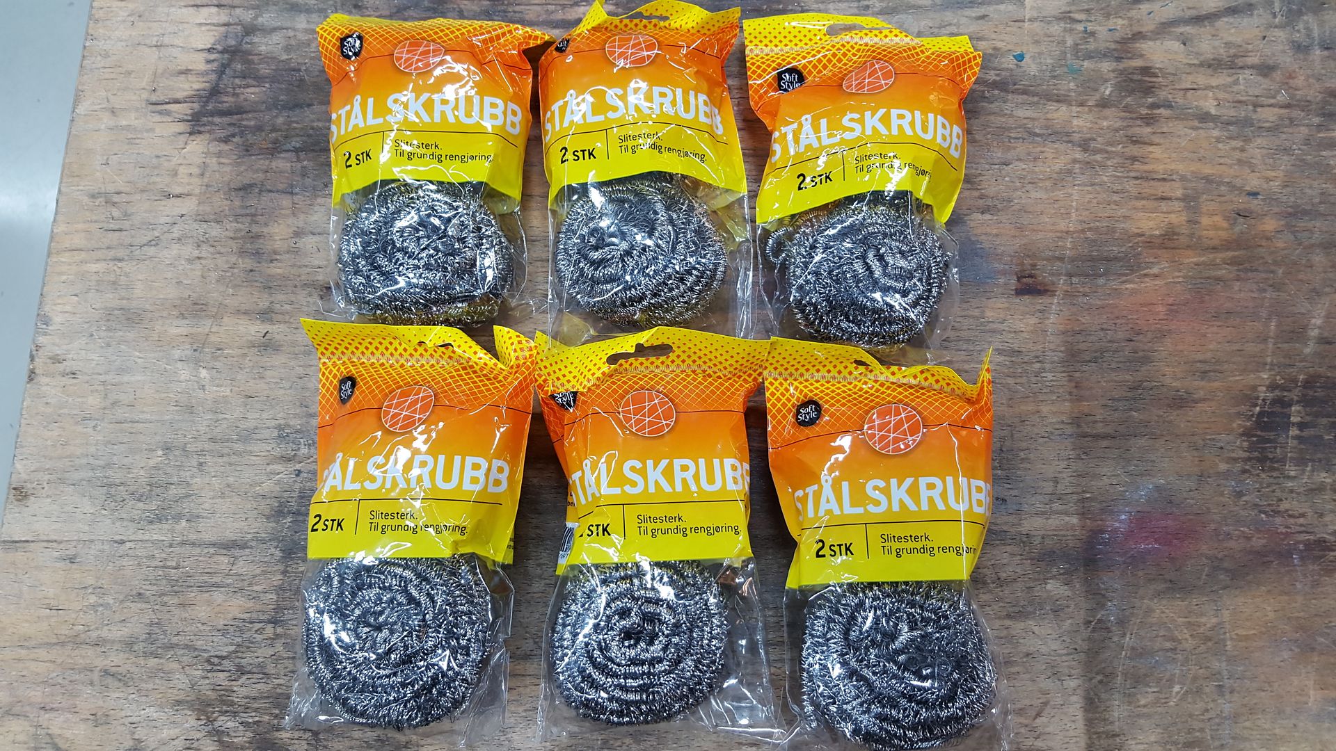
And the filters for the catch can
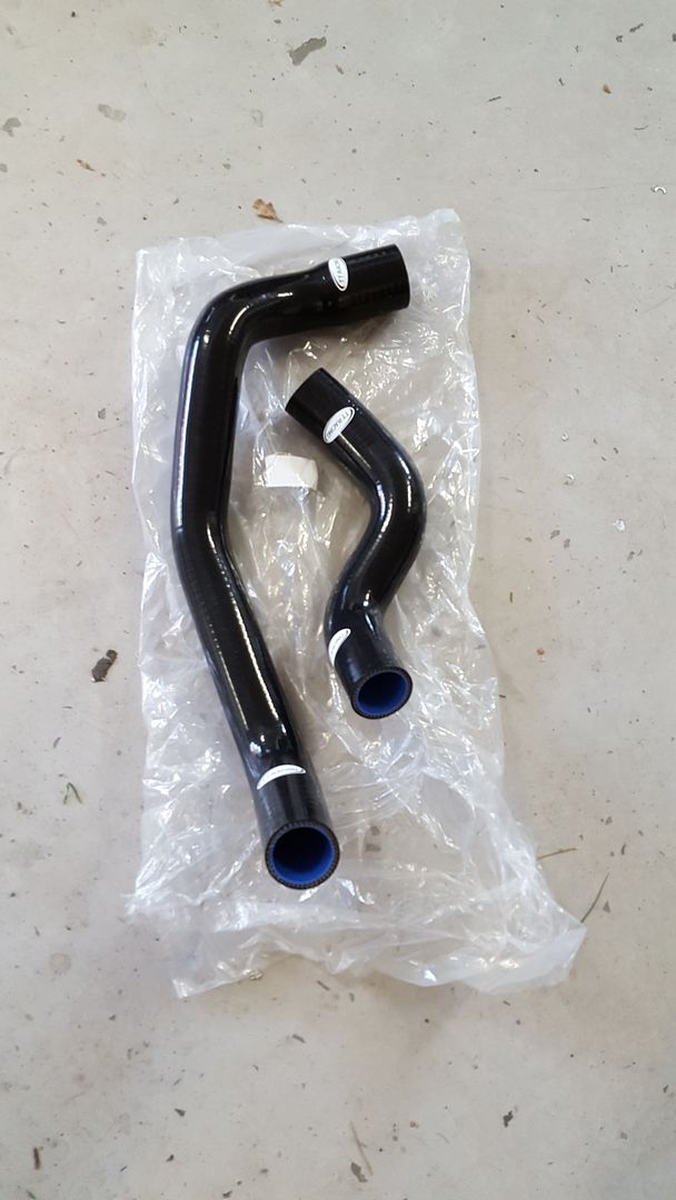
Got some silicone radiator hoses for R32GTR, but I do not think they will fit.
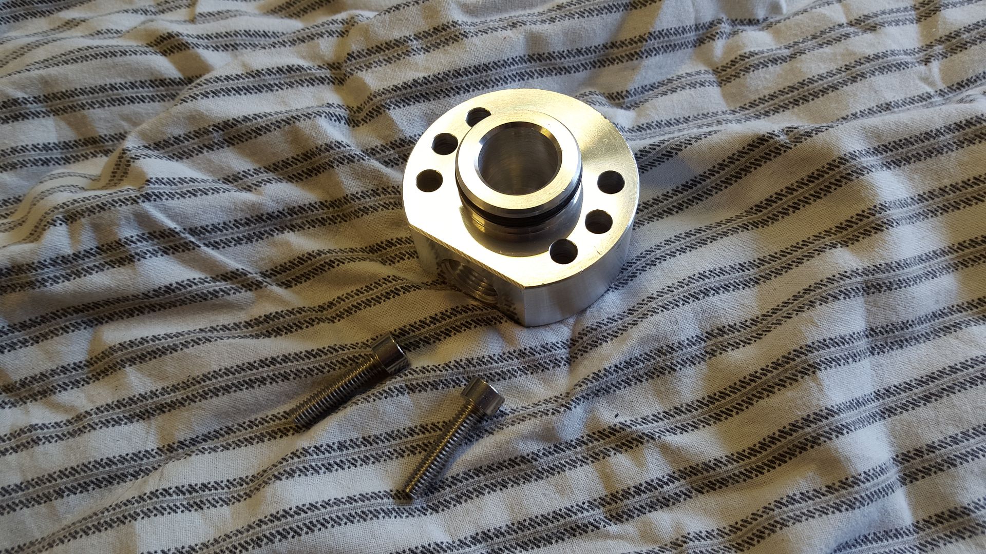
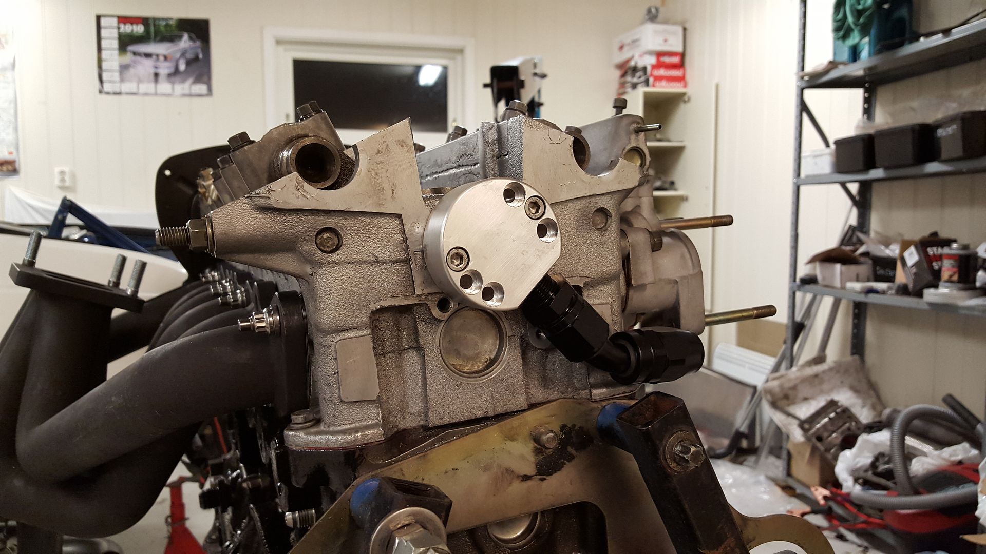
Oil drain for the back of the cylinderhead arrived
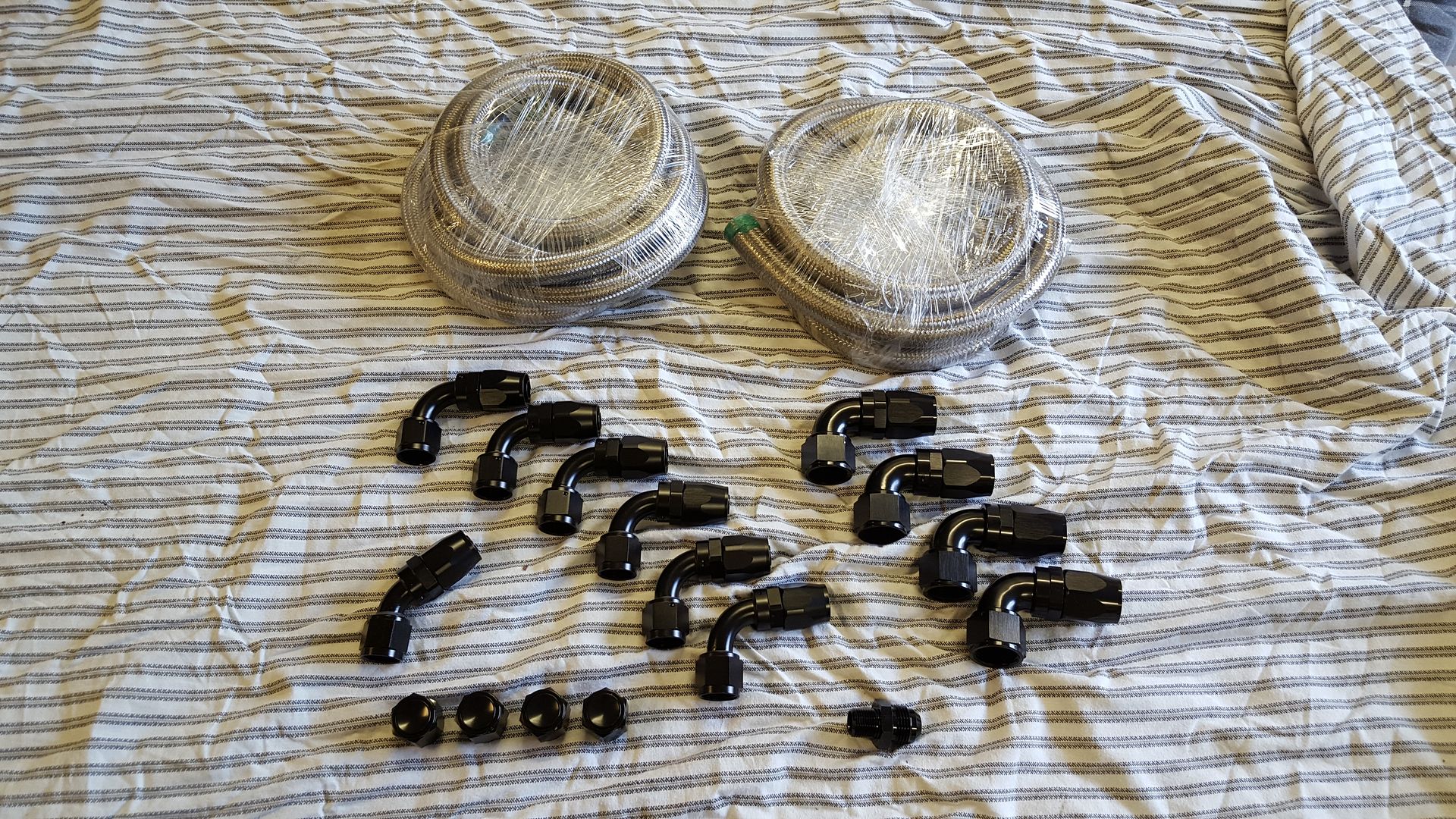
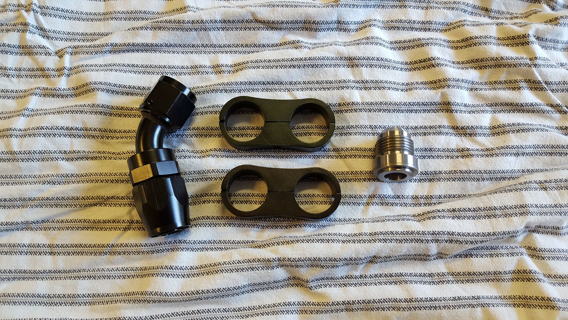
And some fittings. AN10 and AN12.
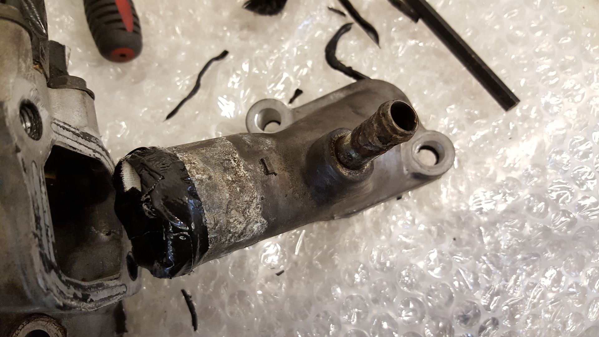
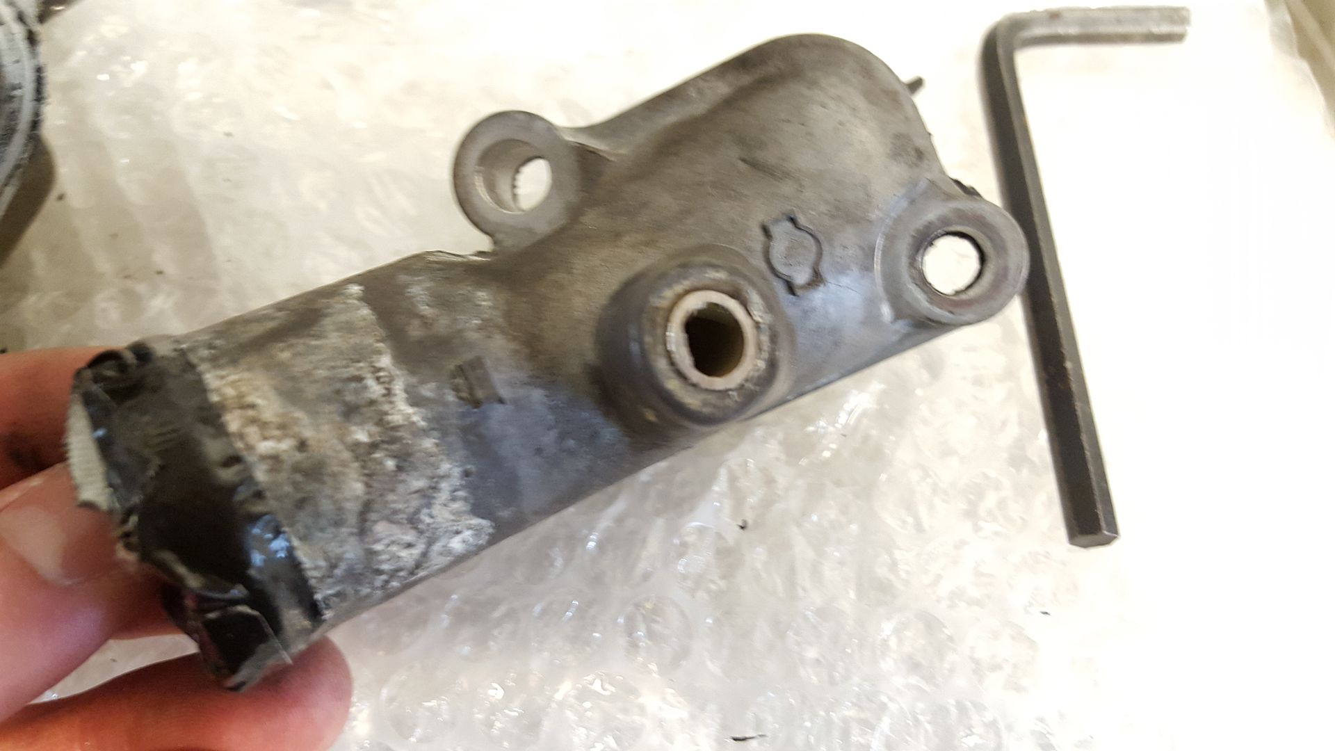
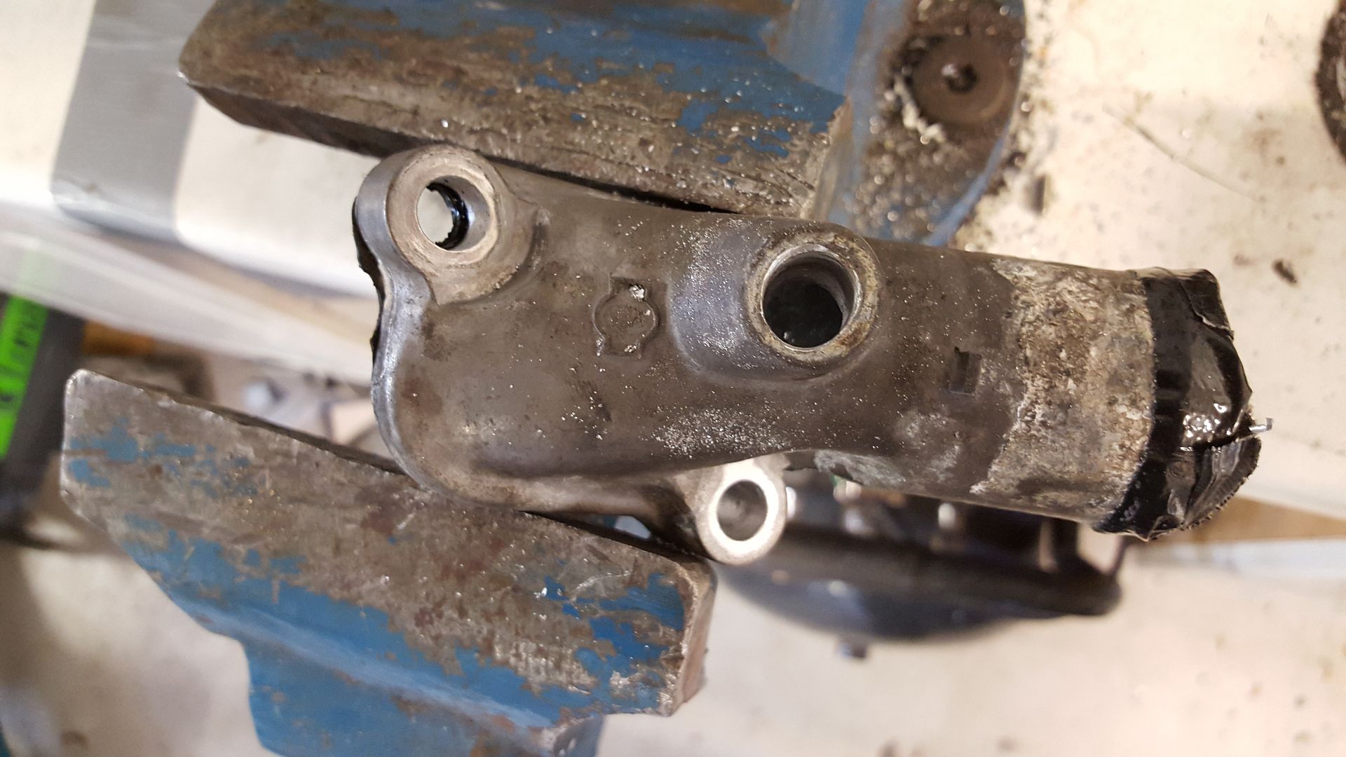
Fitted the head drain
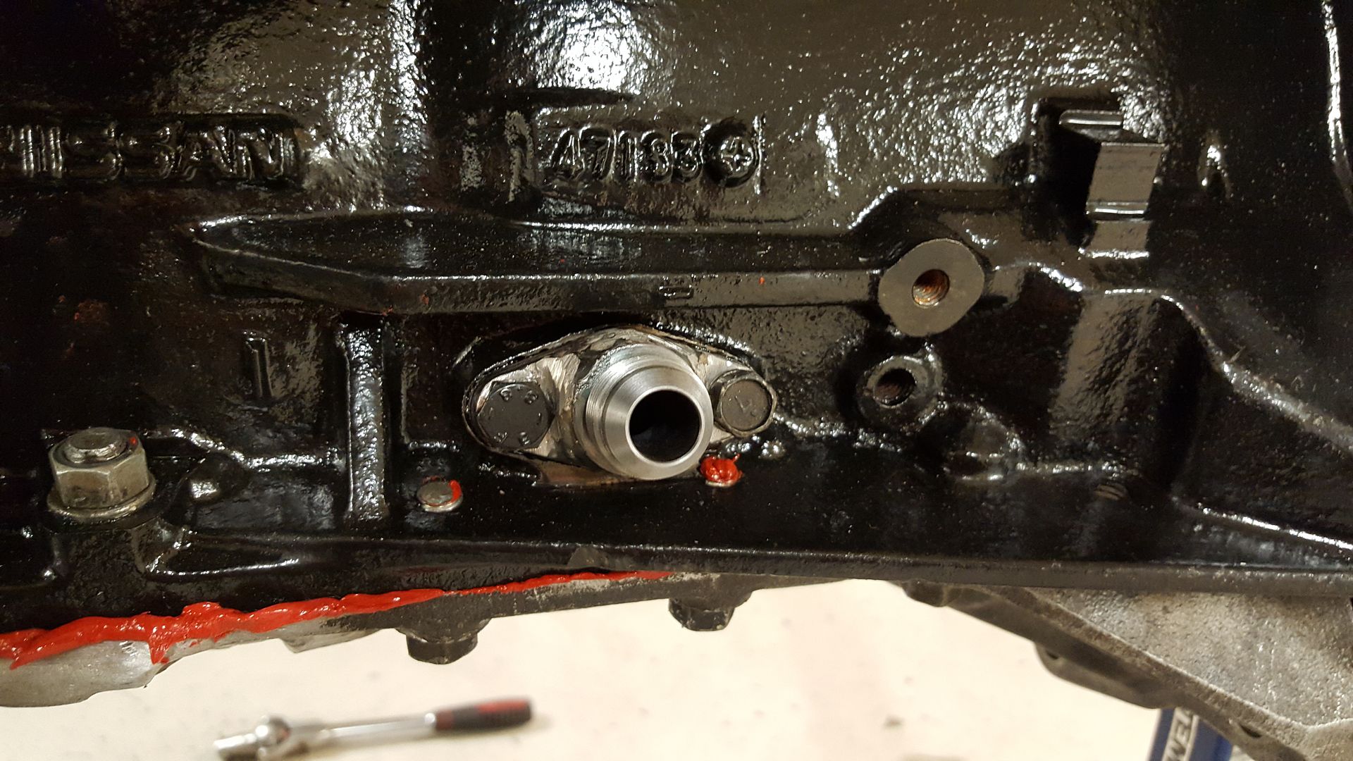
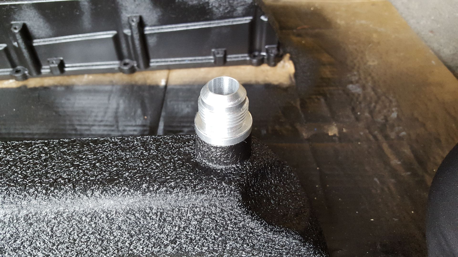
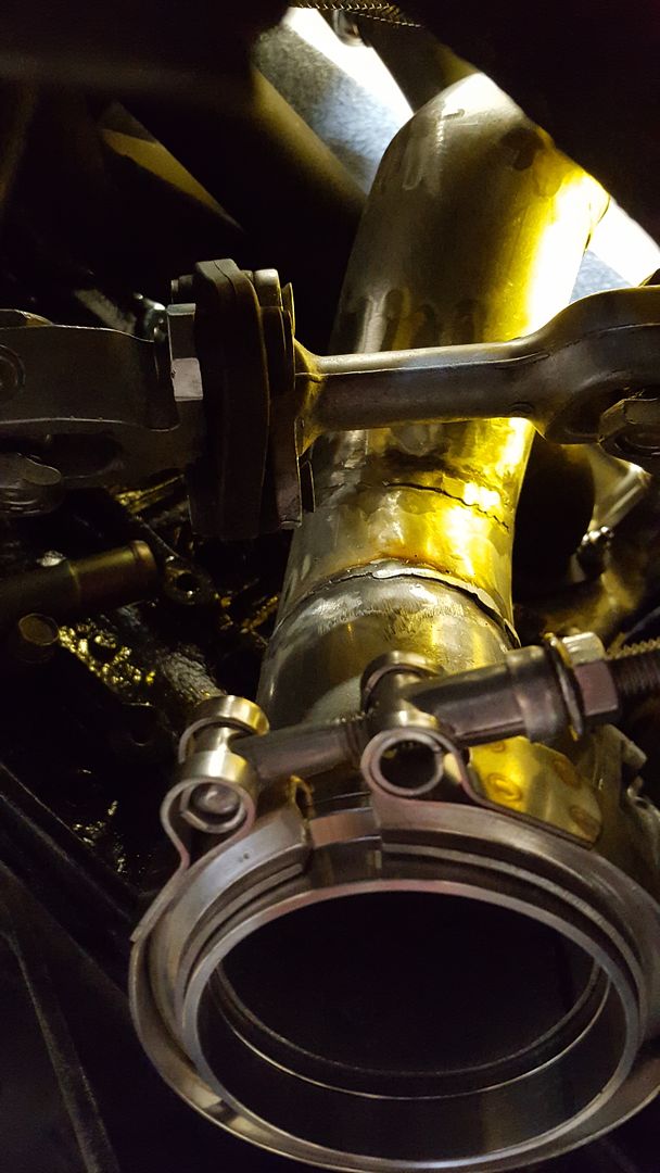
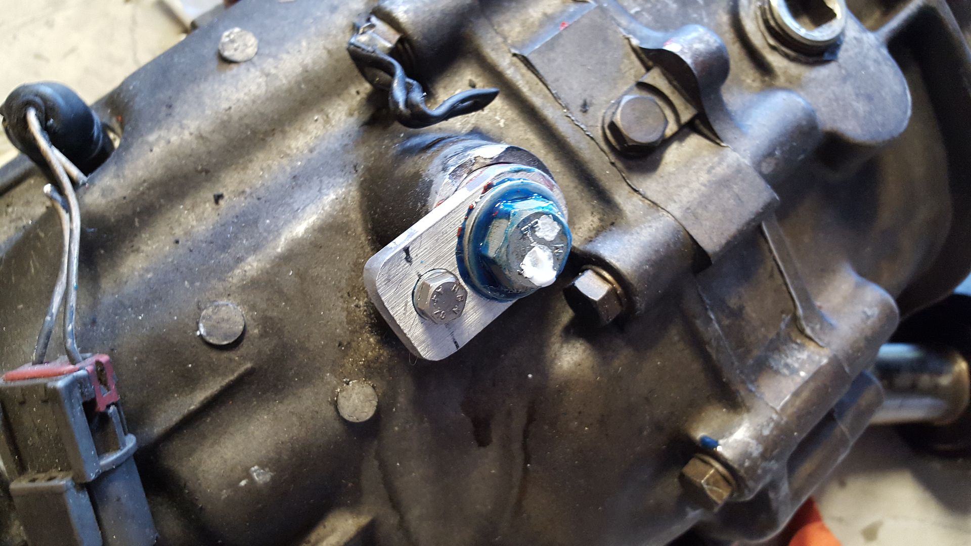
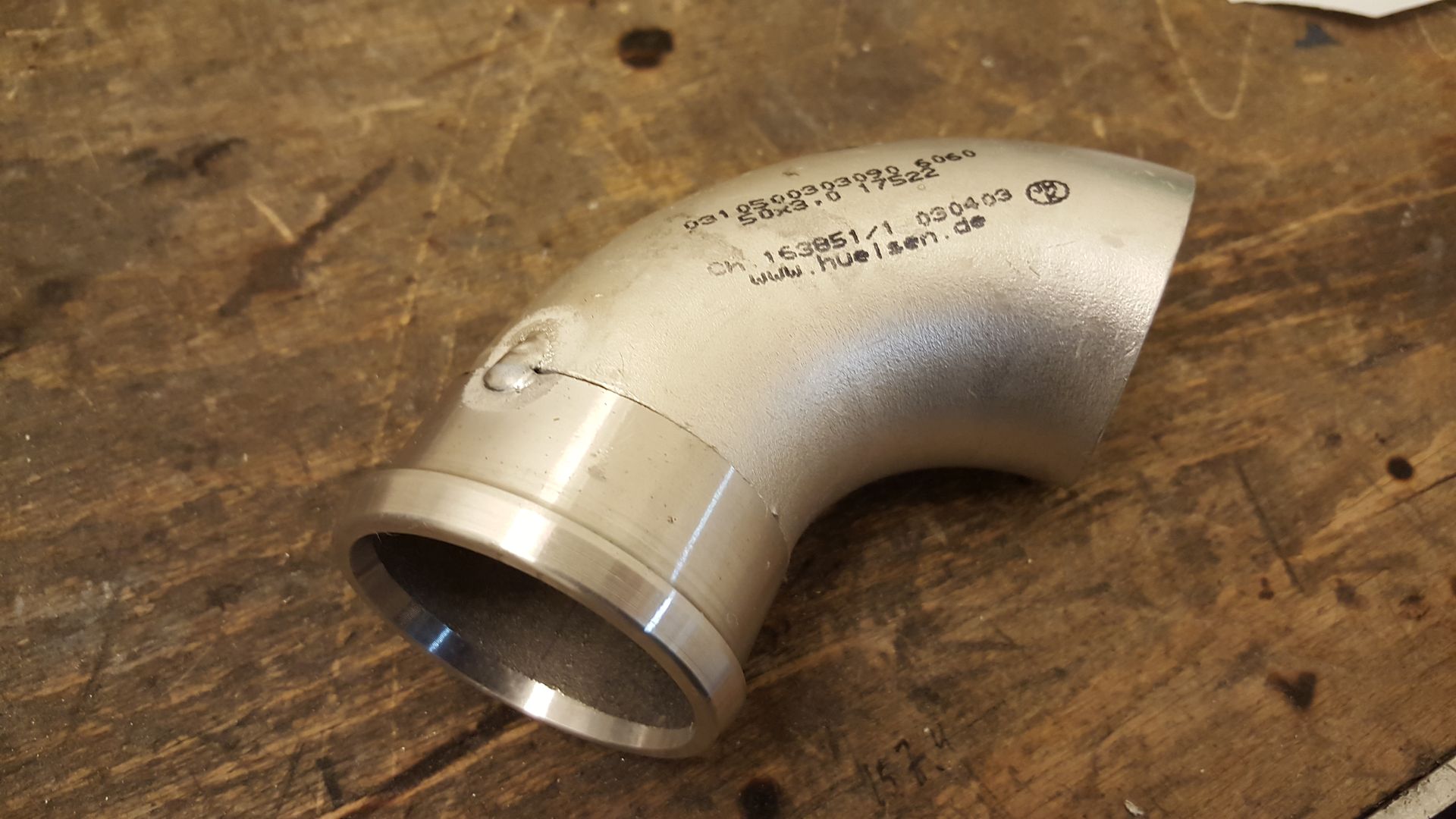
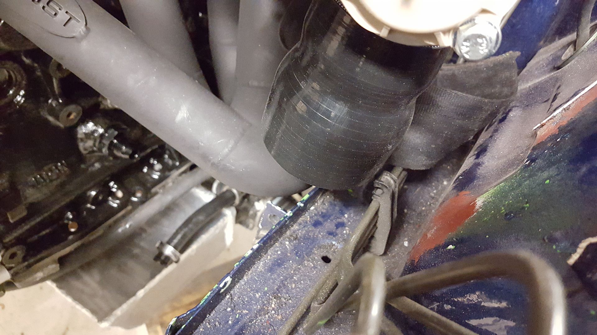
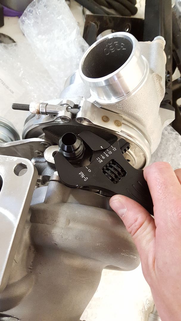
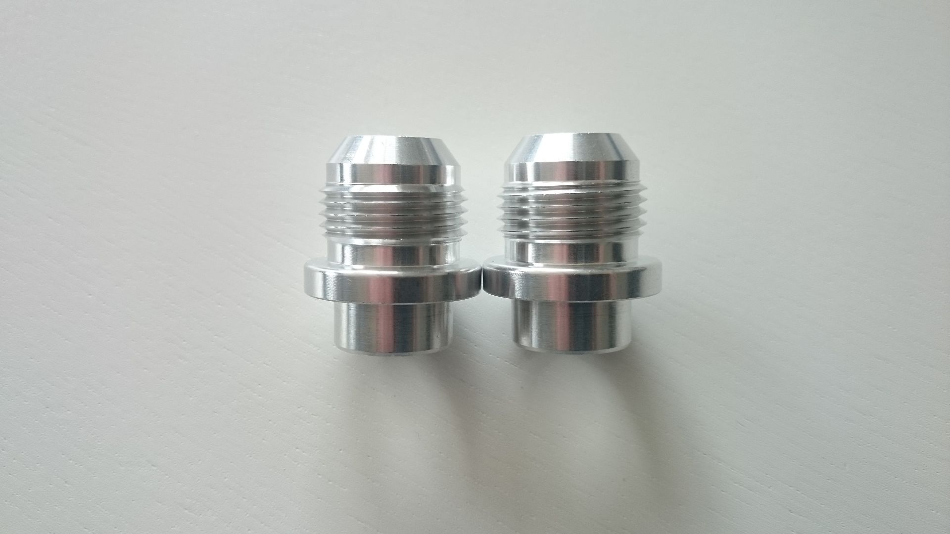
Welded myself an AN10 for crankcase ventilation where the drain for the rear turbo was before.
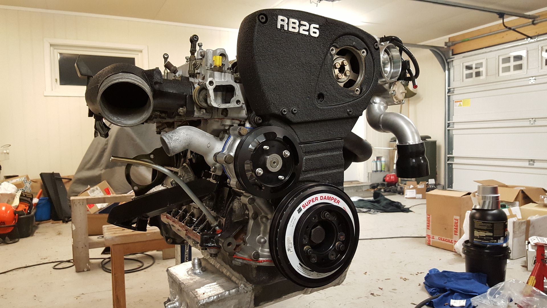
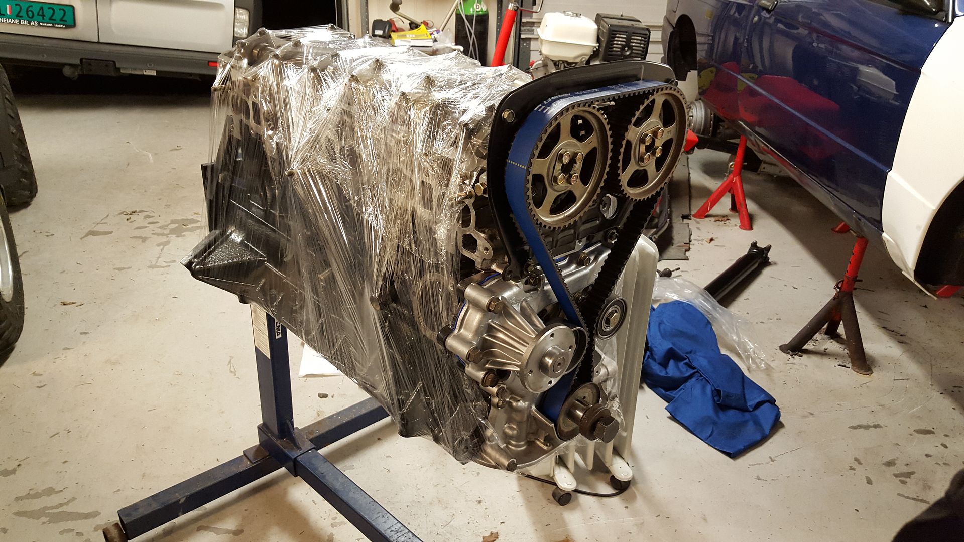
Got the ATI Superdamper torqued to spec and the waterpump pulley. As well as the complete TBS and intake bolted up with gaskets.
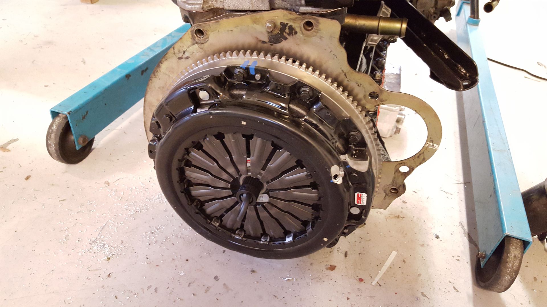
Flywheel and clutch mounted.
And that leves this for the next time I'm traveling to work on the car.
-
 3
3
-
-
Looks so nice.
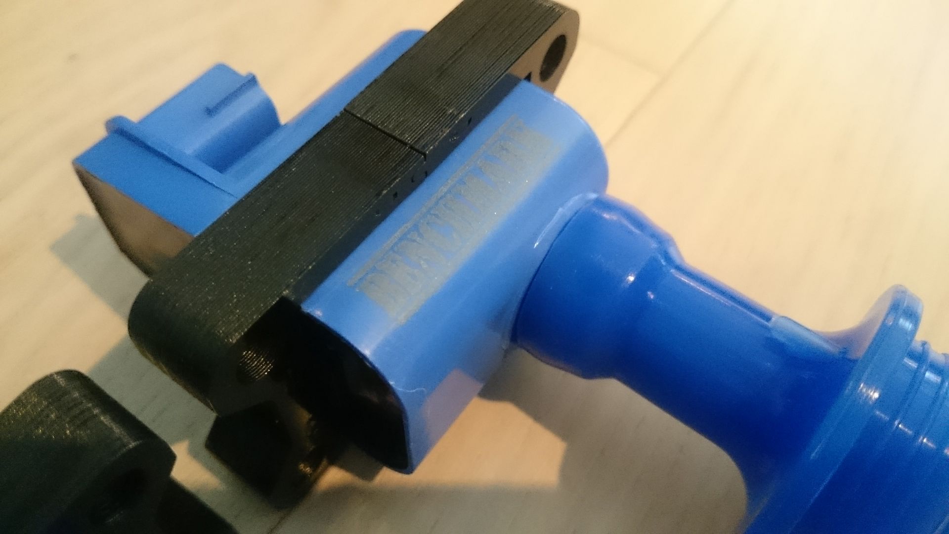
I me very surprised you are using those coils though. Hope they work out ok
Why? After all I have read about coils. These seems to be the one with least problems.
-
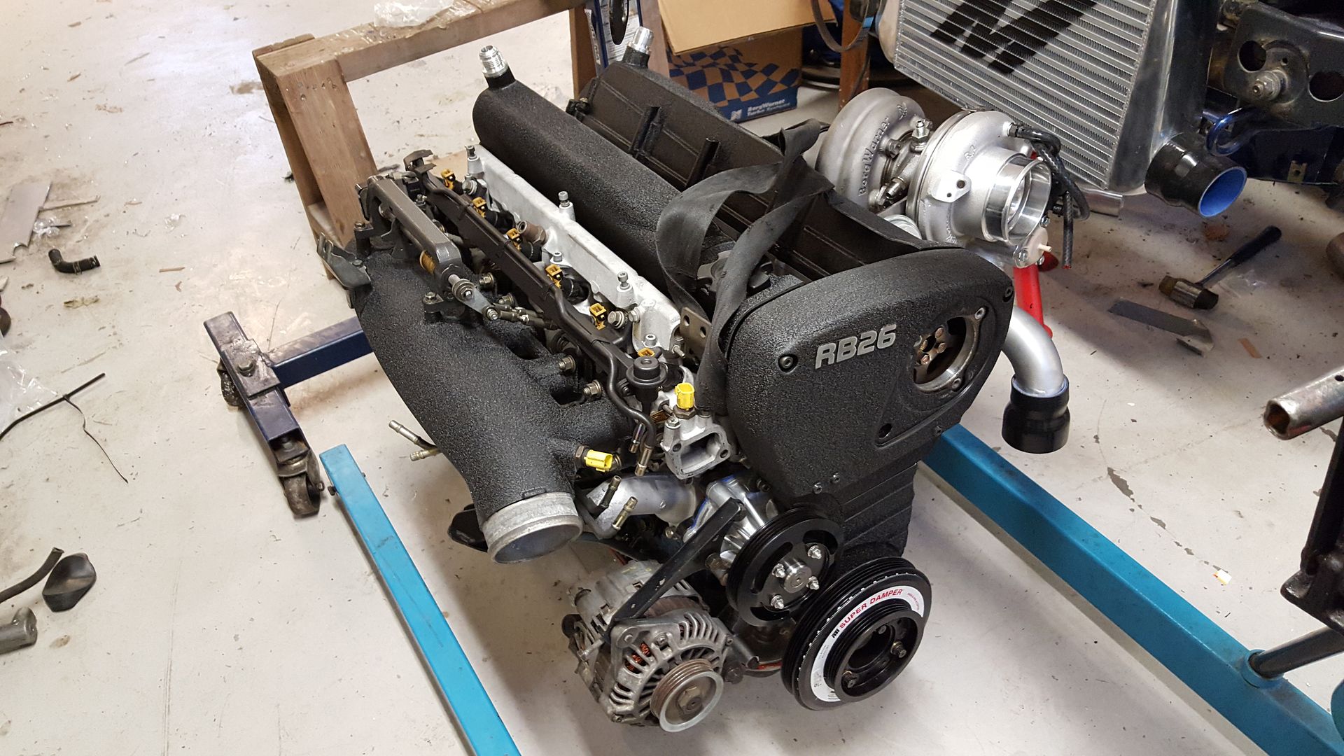
So, I have done some more things
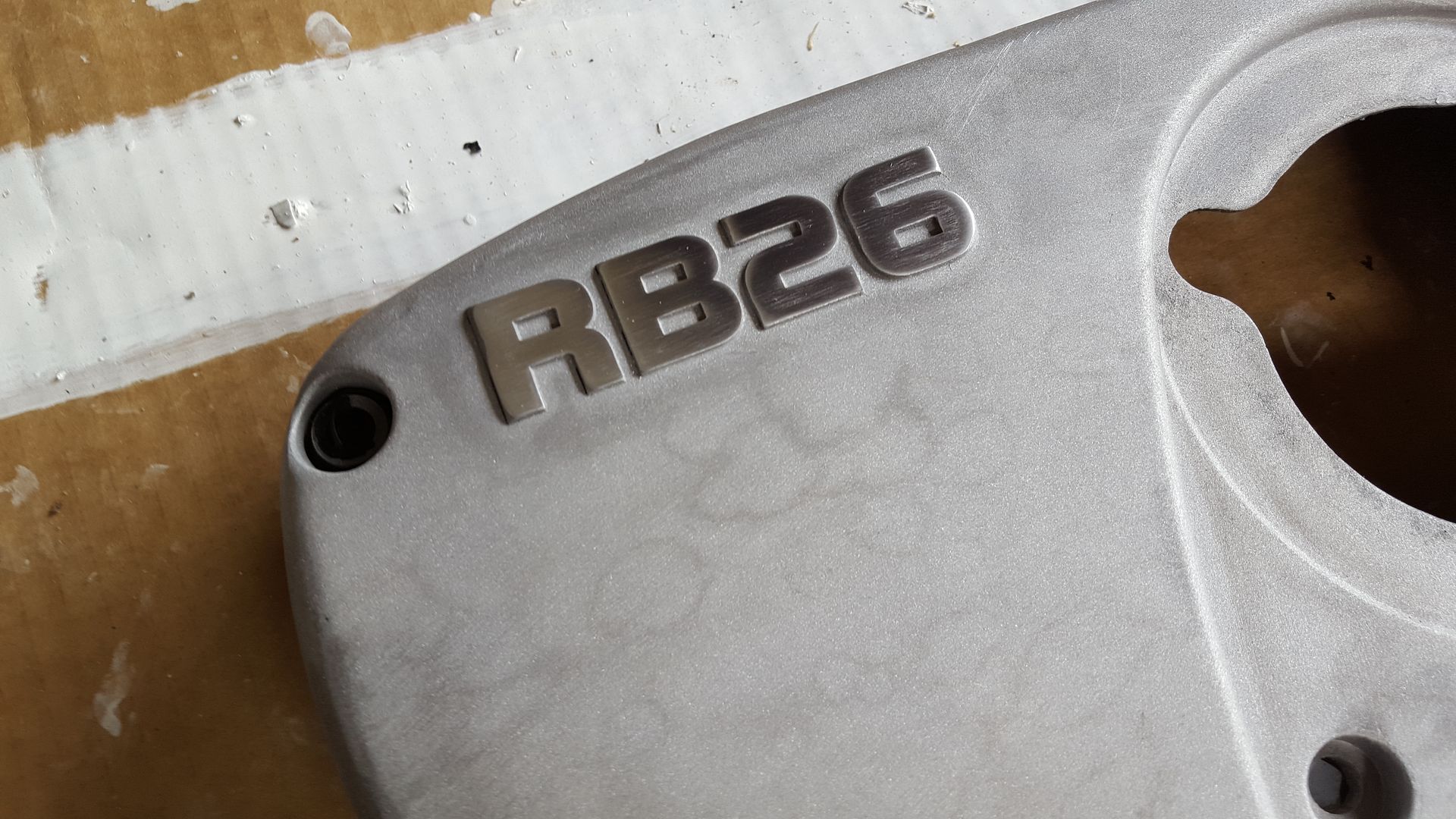
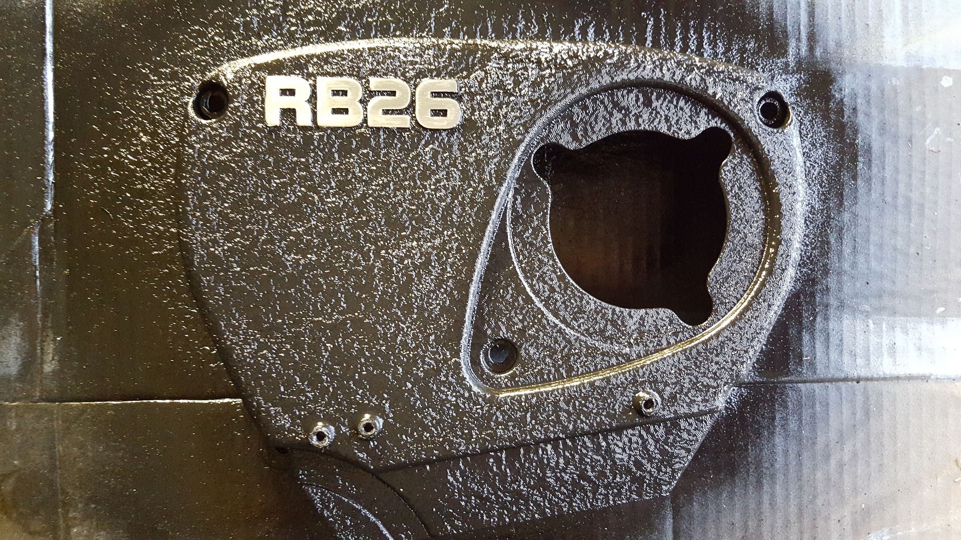
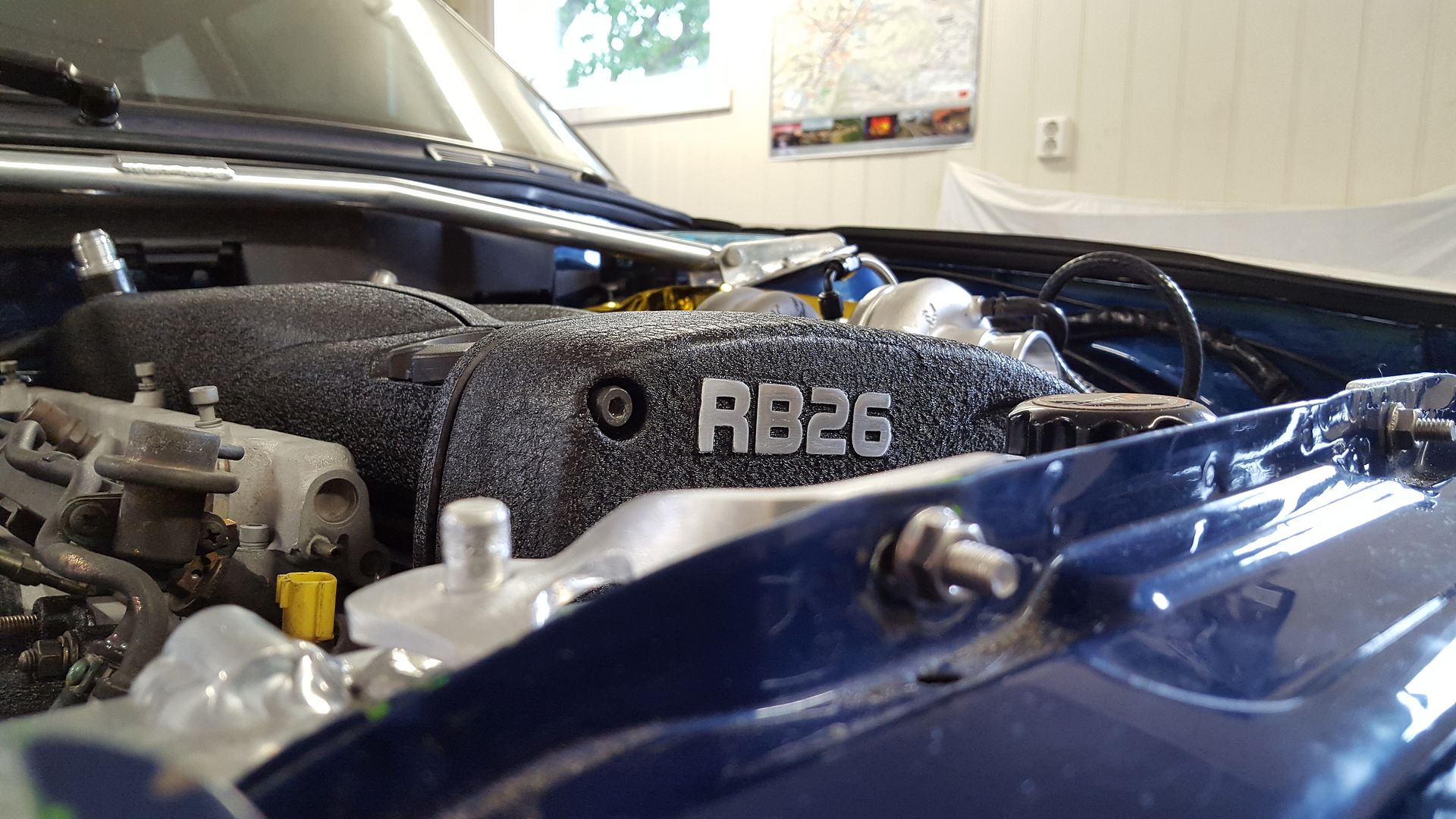
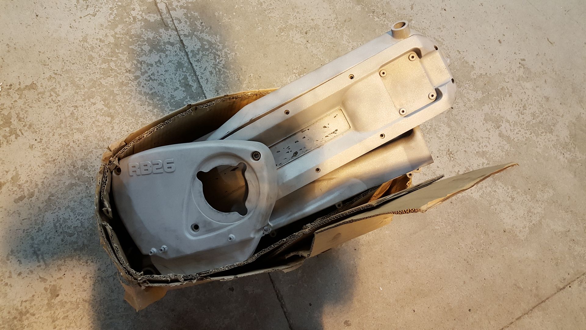
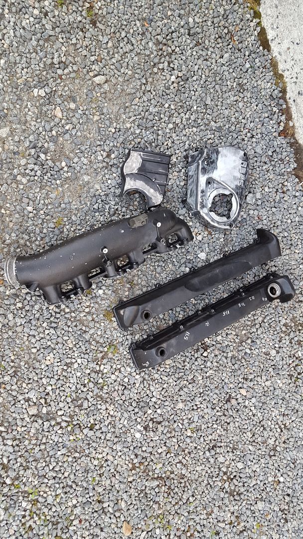
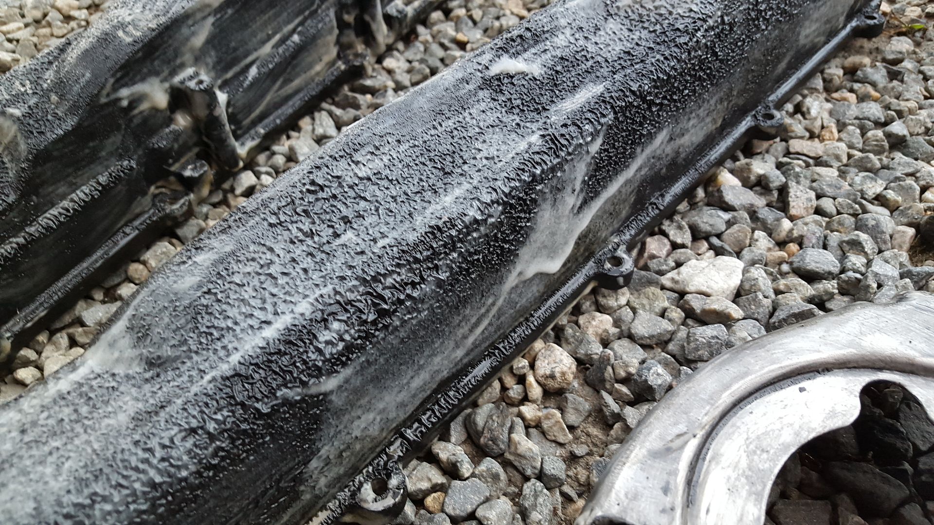
Painted the blasted parts in black wrinkle paint. Started off by polishing the RB26 letters, and had some slilcone on them so the paint would not stick.
Painted
Mounted the AN12 breathers
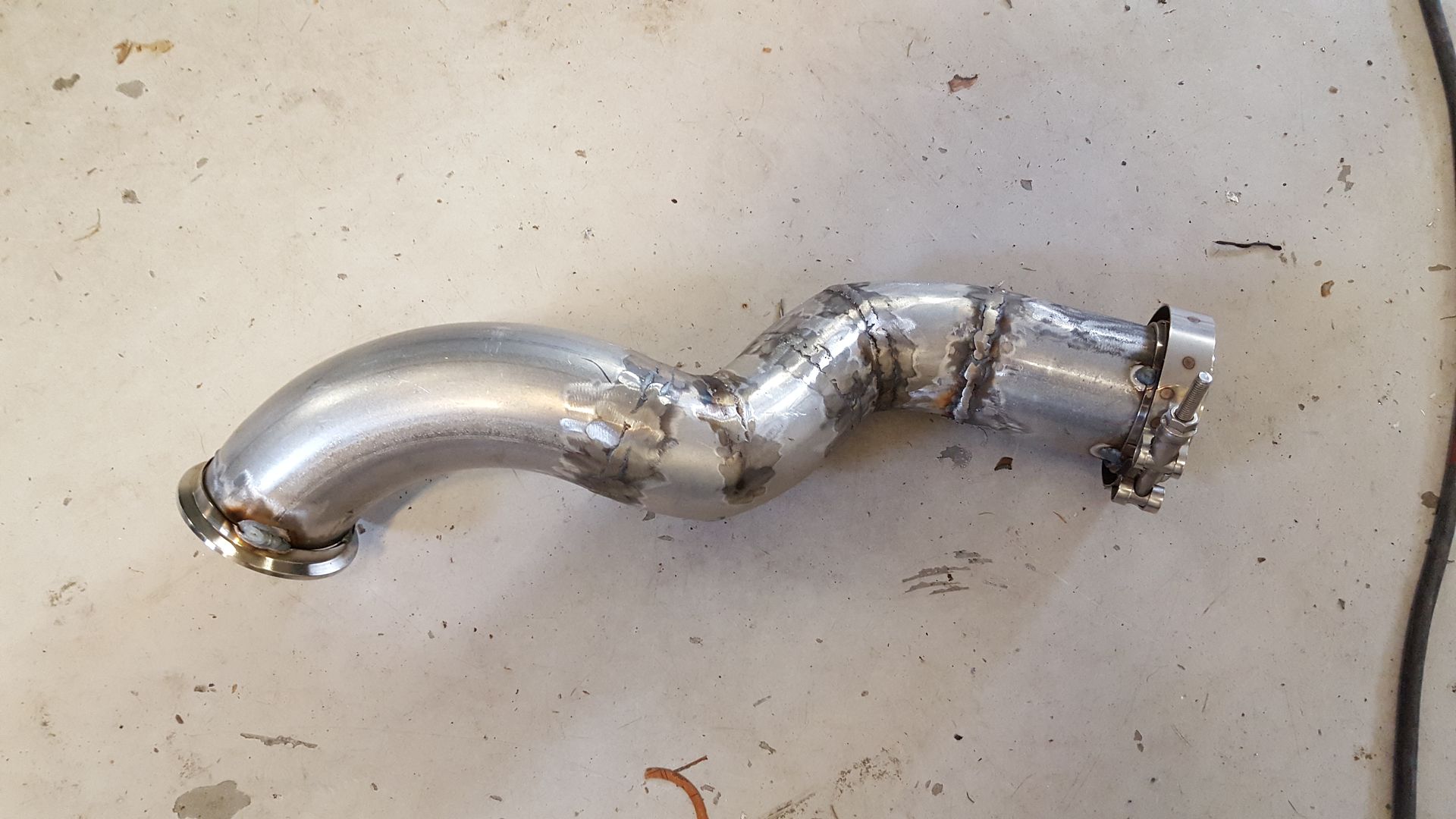
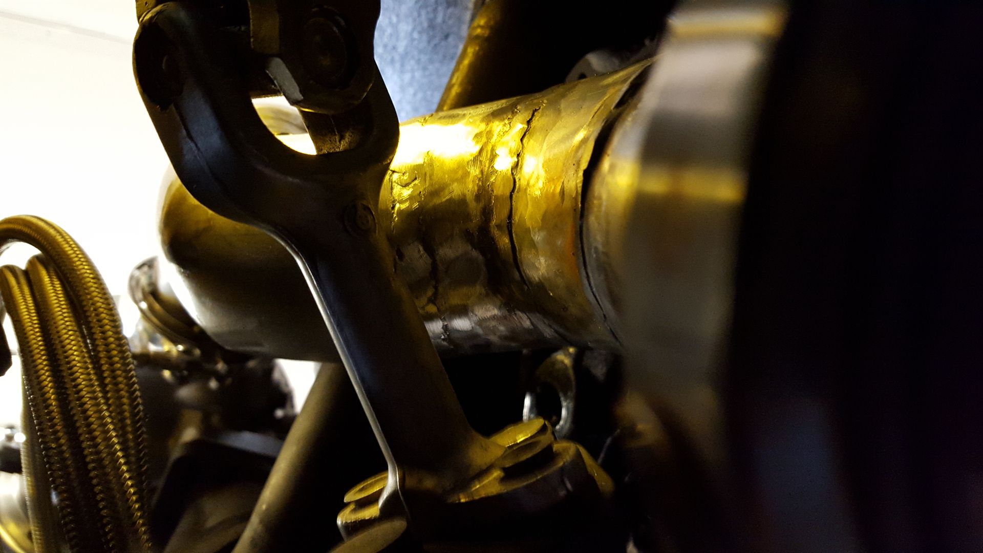
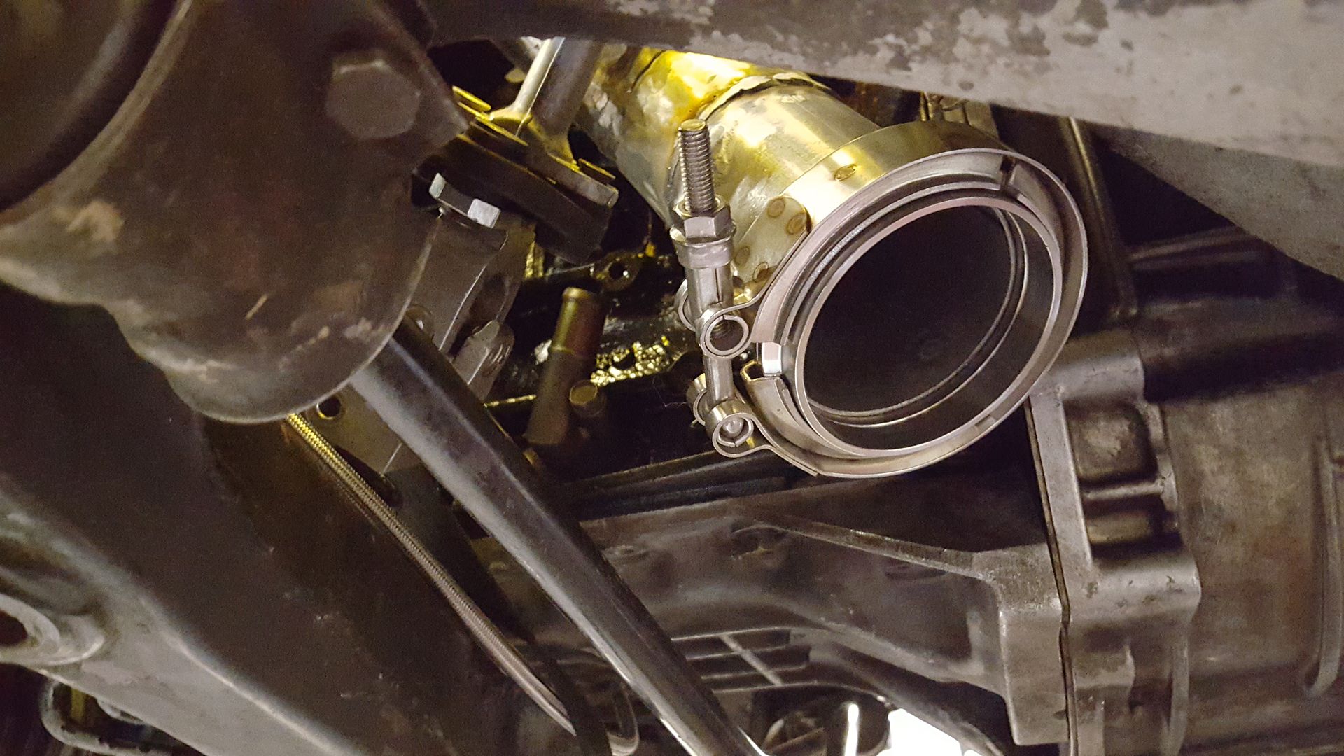
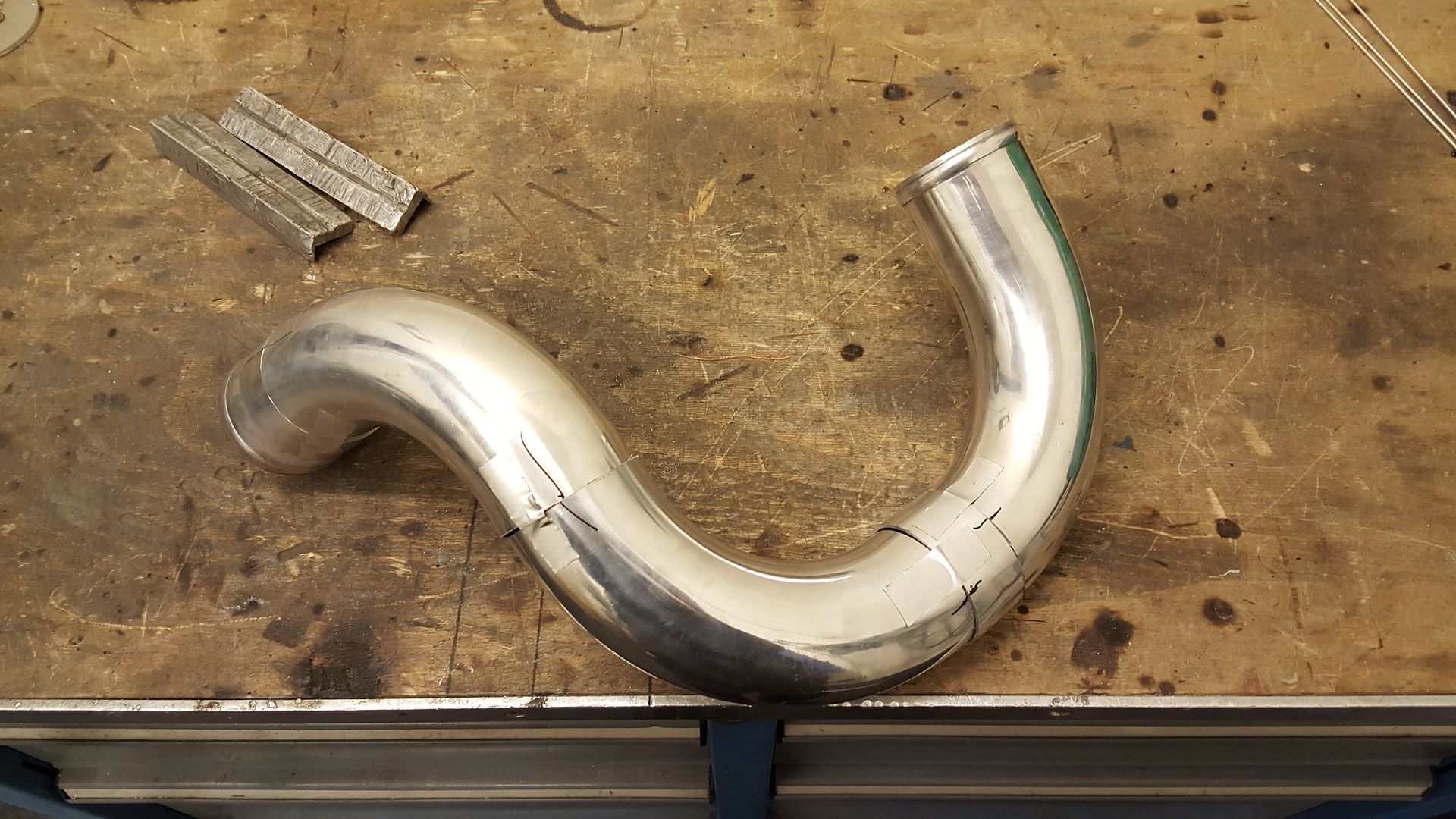
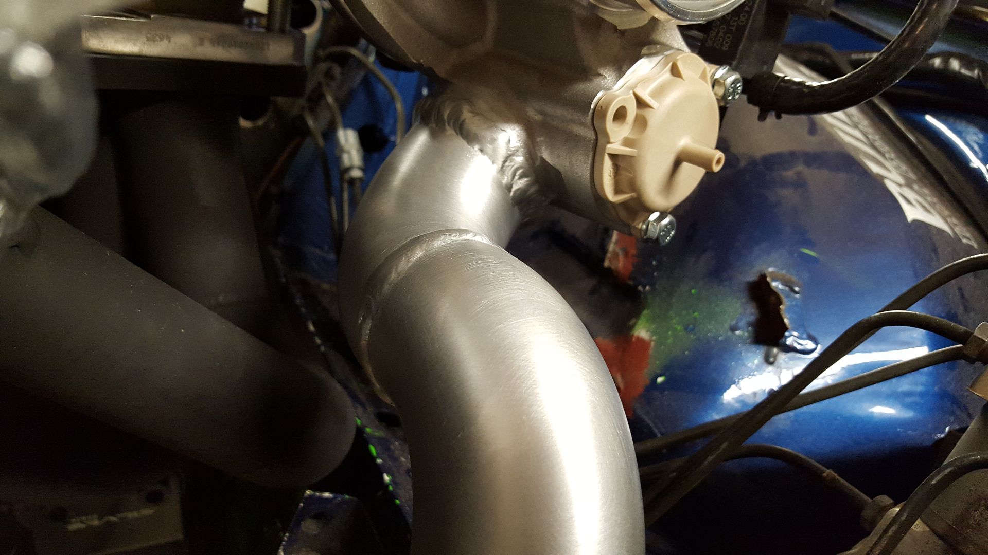
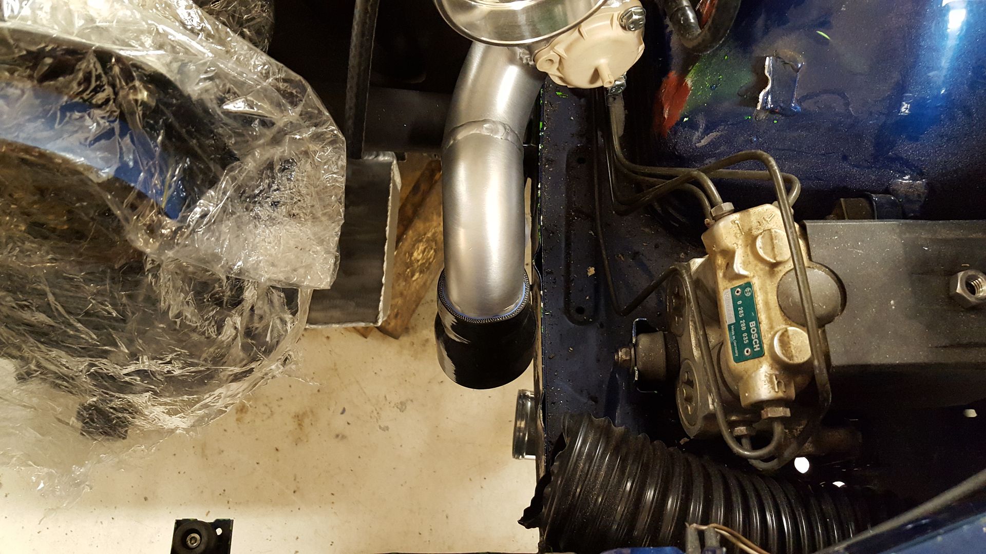
Then, I started to build the downpipe. I started this friday evening and did not get f**king anywere. My mind did not work. So I called it the night, and just watched some tv series instead. So today I started fresh and it all came down to me quick, so after a couple of hours I had buildt the downpipe.
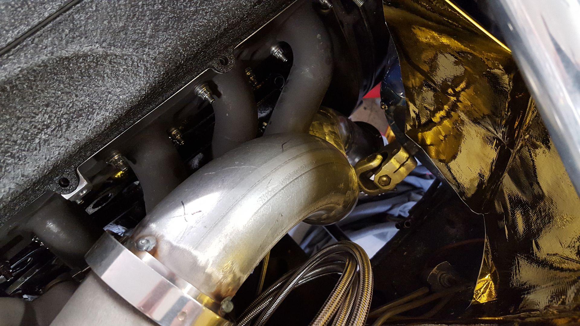
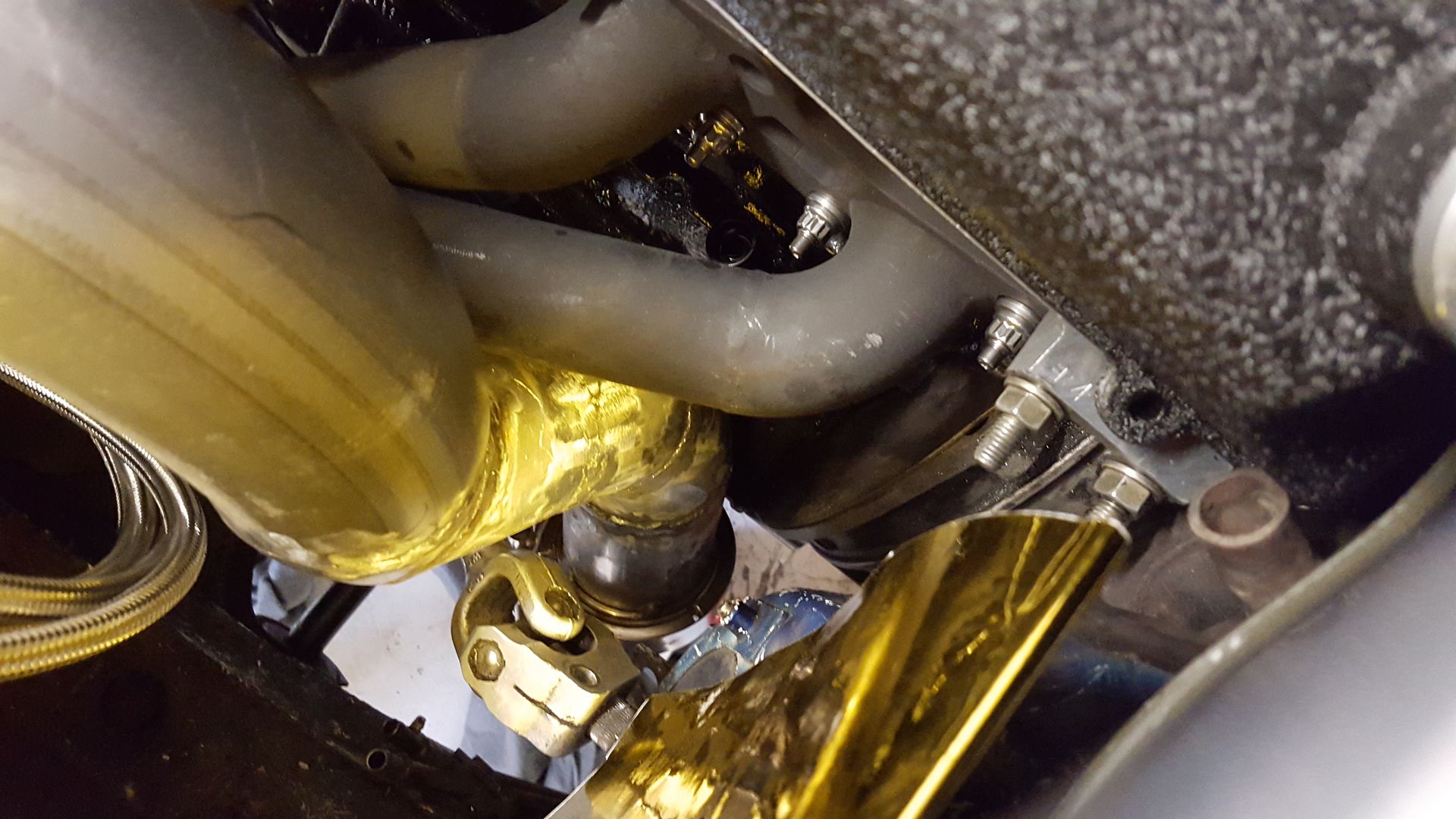
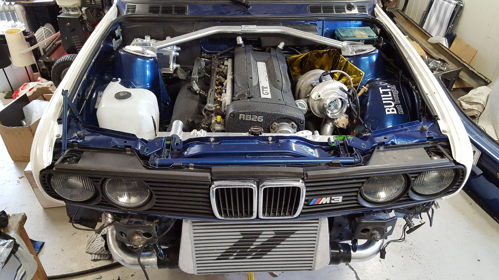
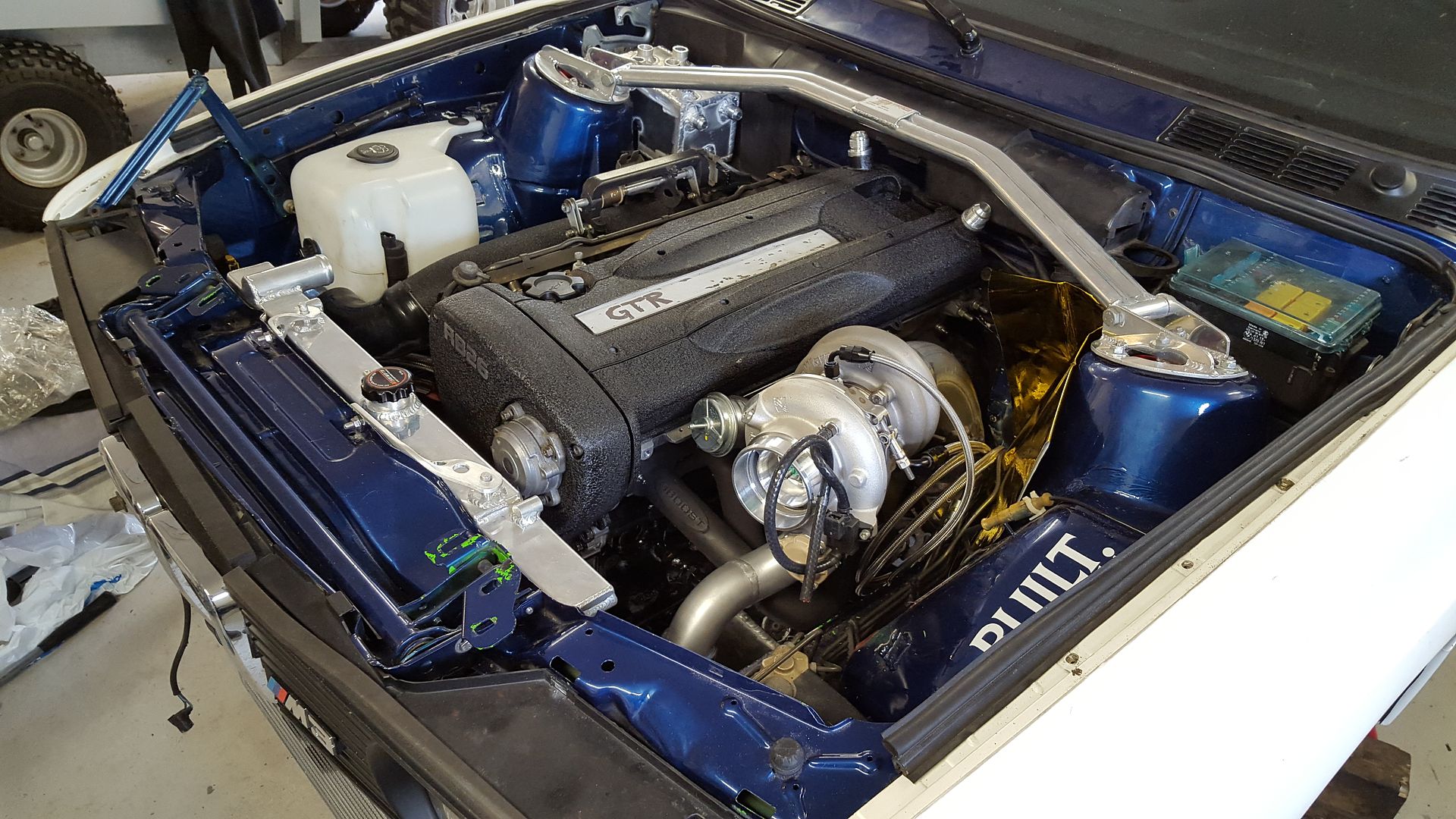
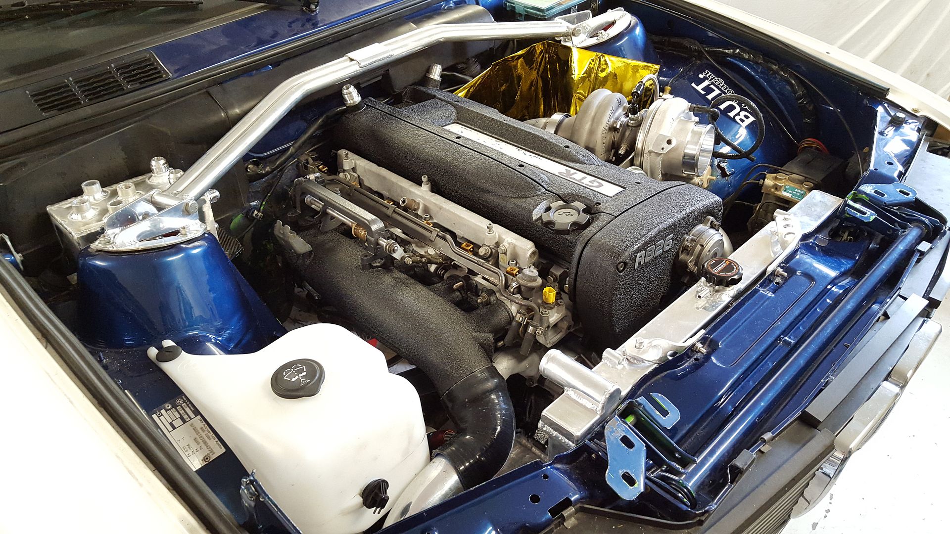
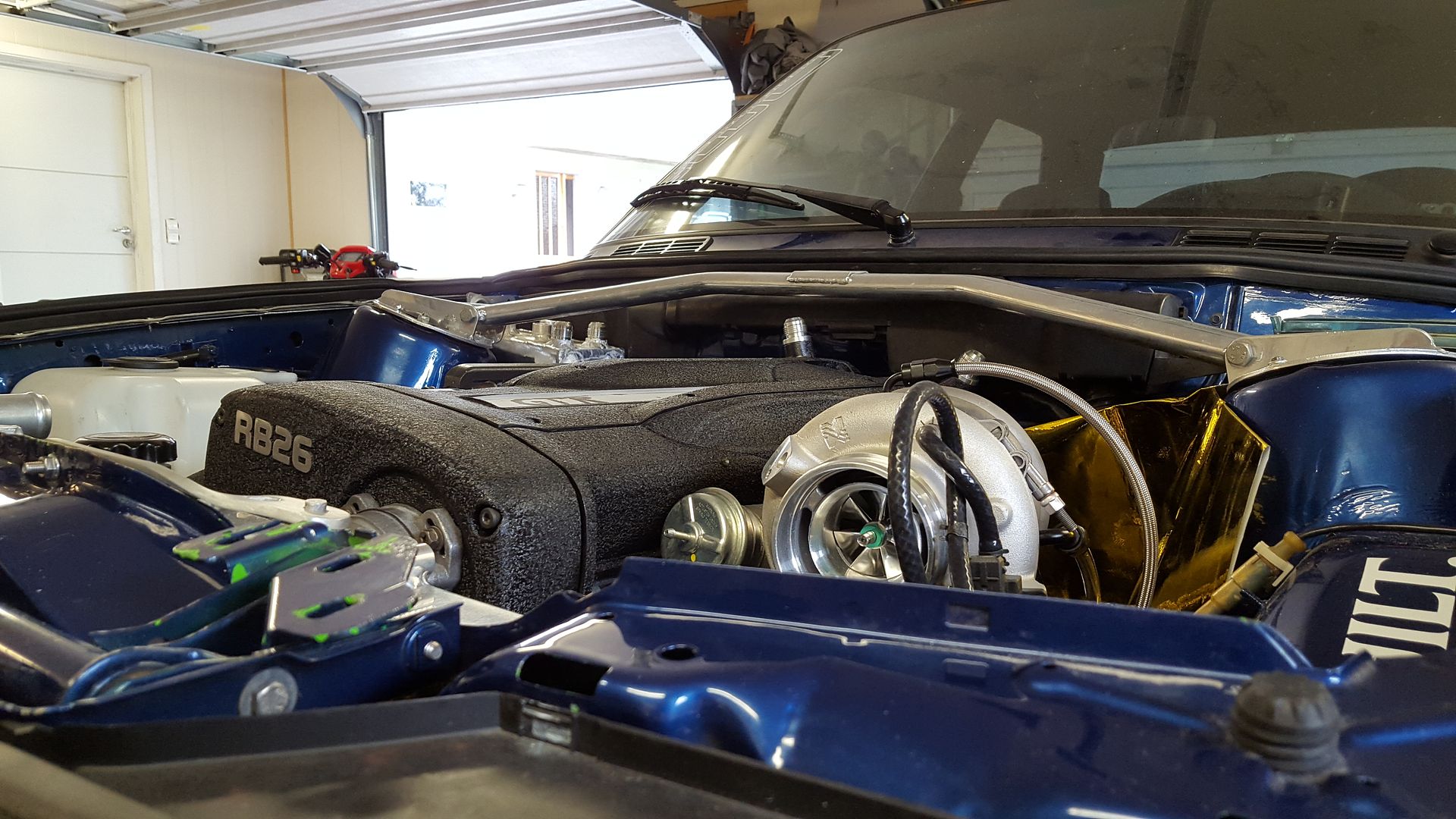
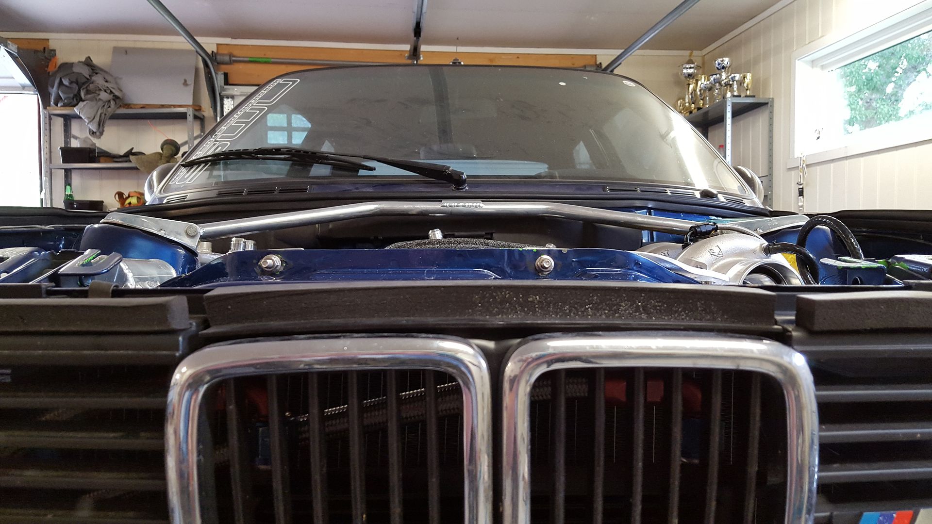
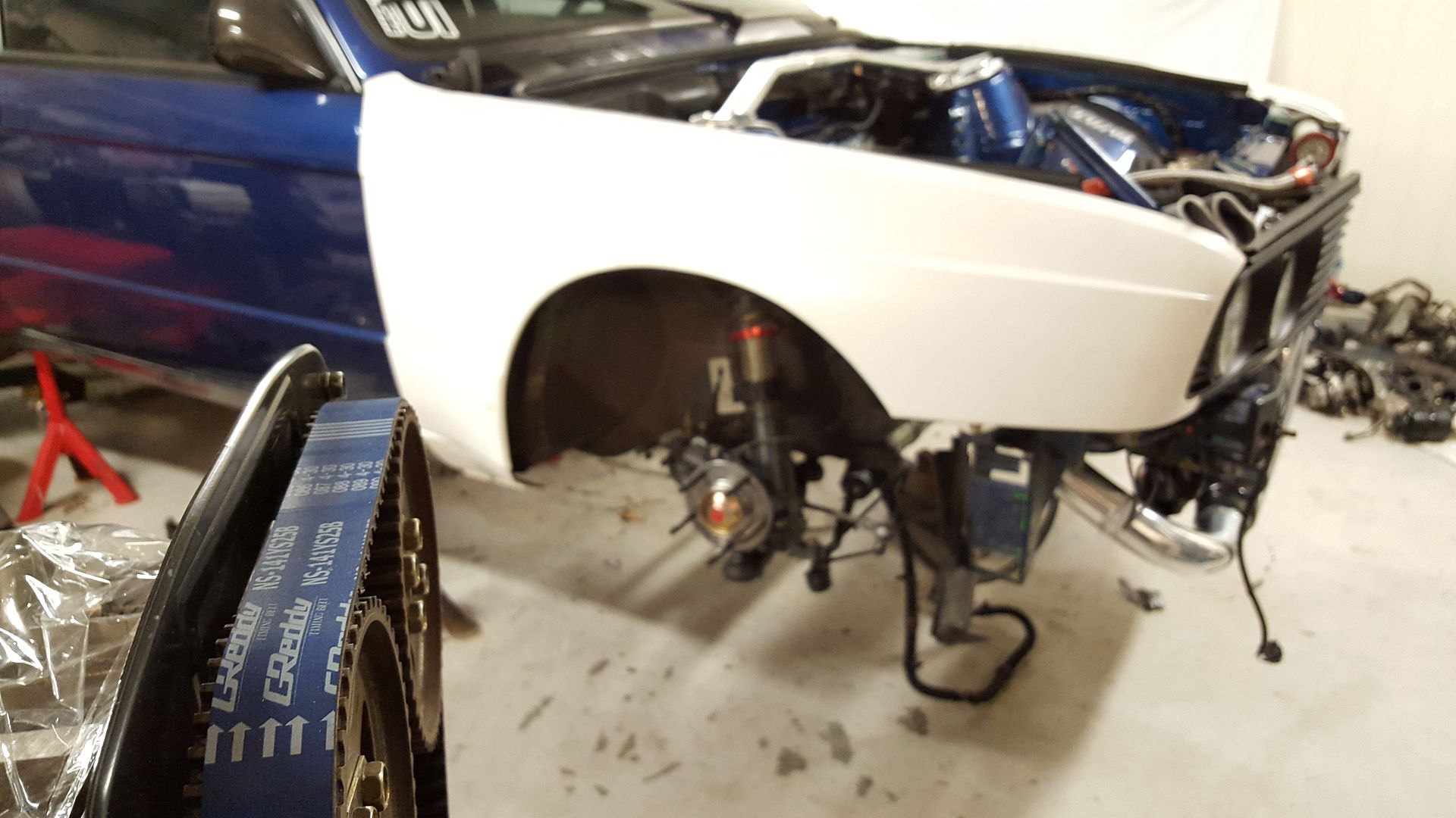
I then wiped some dust of the engine bay and mounted the painted parts to get a look at what the final product might look like.
Sits pretty low in the bay. Good for lower center of gravety.
That is all for now. There will be some weeks before next update. Untill then, take care and stay tuned for the next one. Tanks.
-
4
-
-
Ok, so, time for update again! As sad as it is, I'm moving to another place this weekend. And the car will continue to stay where it is for now. That leaves me with about 2.5 hour drive to get to it. So there will be less progress here from Saturday and on.
I just have to use the weekends to get shit done before the winter kicks in and it is getting to cold to do anything. So this is the reason why I have kicked in an extra gear these few weeks. Staying in the garage from 3pm to 11pm.
Getting more and more things done here, and I'm starting to see an end to this. I have engineered a lot of custom parts for this build, that is things I have never done. I have always done things that other people do, but this time it was my turn to invent the wheel.
I'm the type of person that want to help other people find information on the web. If you want to build a proper RB26 swapped E30, I want you to find the answer to all your questions here. But I assume most people toss the idea away once they see all the work it require.
What have I done since last time? I have build the intecooler pipe from turbo > Intercooler, cleaned the sandblasted parts for sand and dirt, finished the oil catch can, assembled the first half of the intake manifold and made the plug to the speedometer sensor on the gearbox.
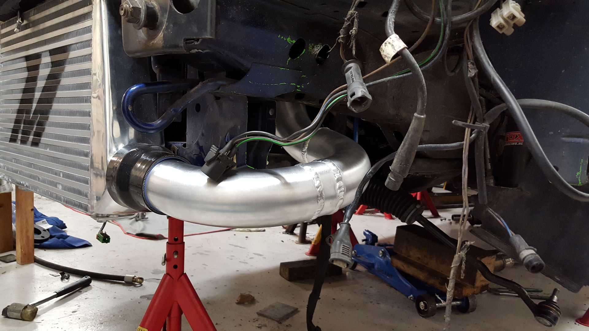
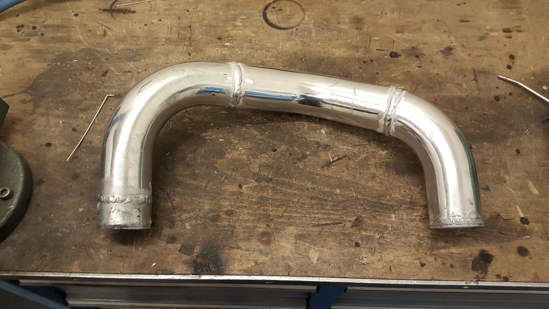
So, let's start with the intercooler pipe. I'm actually not happy with how it turned out, but it will do the job for now.
To get this finish on the pipe I used steel wool.
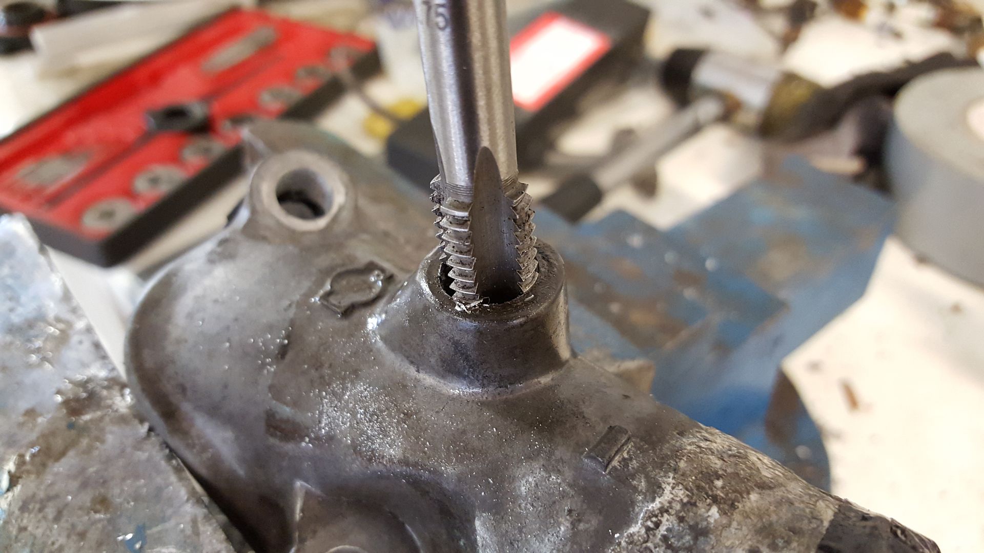
For the gearbox I just made this really quick. Tapped the hole, put in Loctite and high temp RTV silicone for sealing.
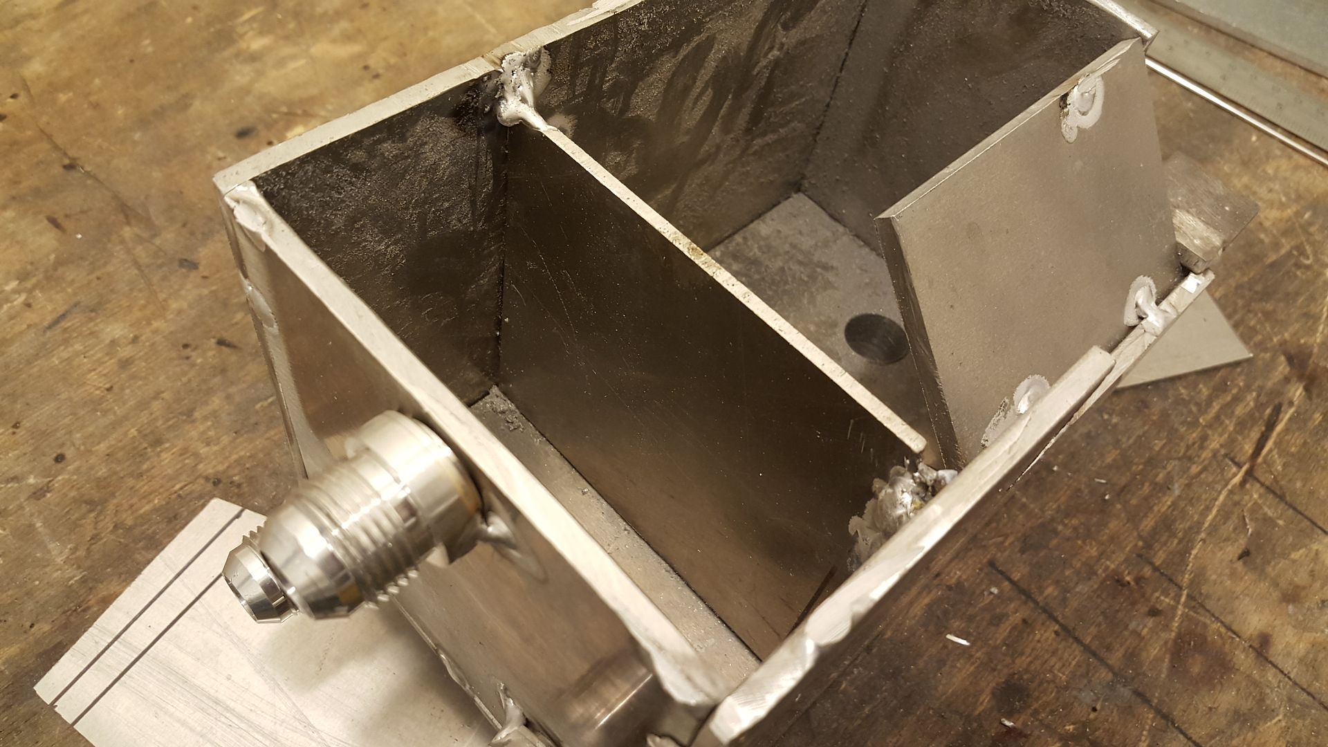
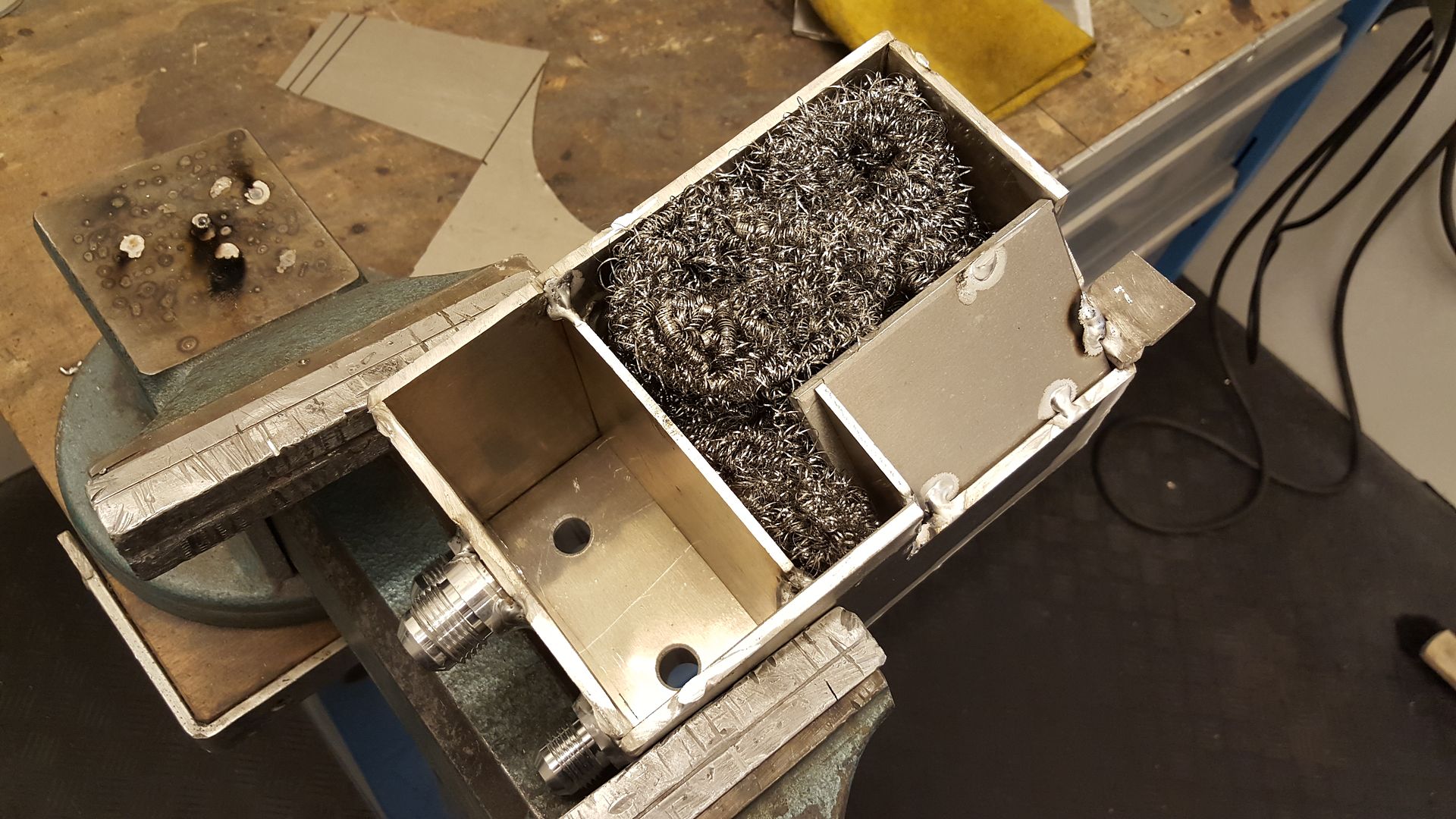
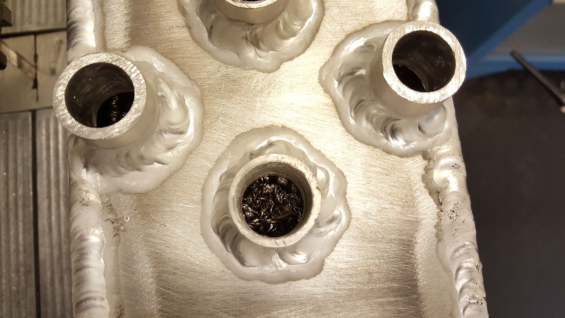
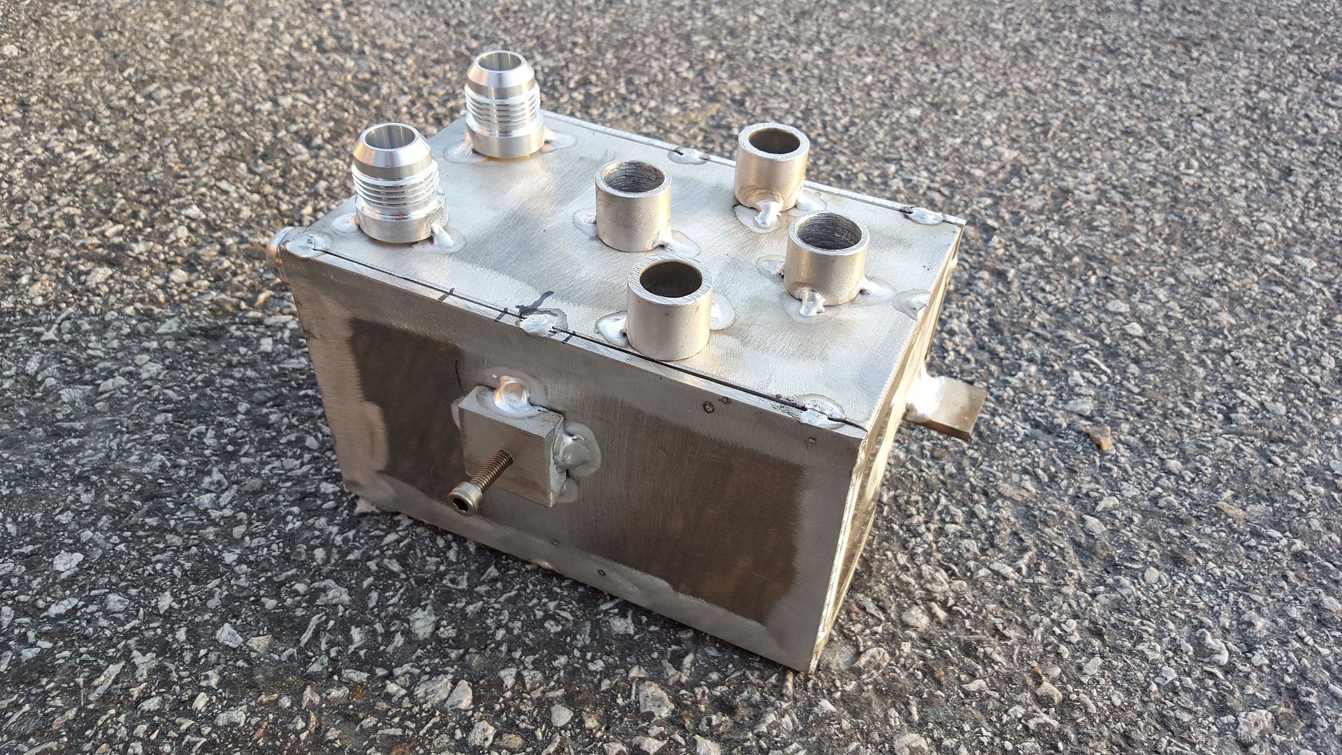
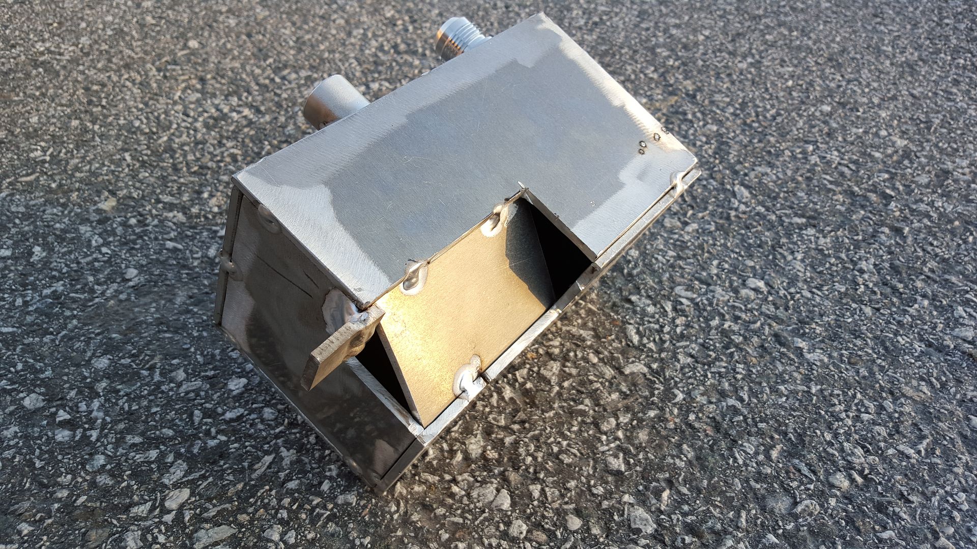
The catch can is another story. I had no clue on how these was supposed to look inside, and no one could ever give me a proper answer to how I should build it eater. But I understood that the hot oil / vent needed to hit a flat surface before exiting the can. To get that effect I spot welded a plate inside the can, and there was also needed stainless steel wool as a "filter" for the steam or what I shall call it.
So I opened the can and spot welded the plate.
I then continued to seam weld the can
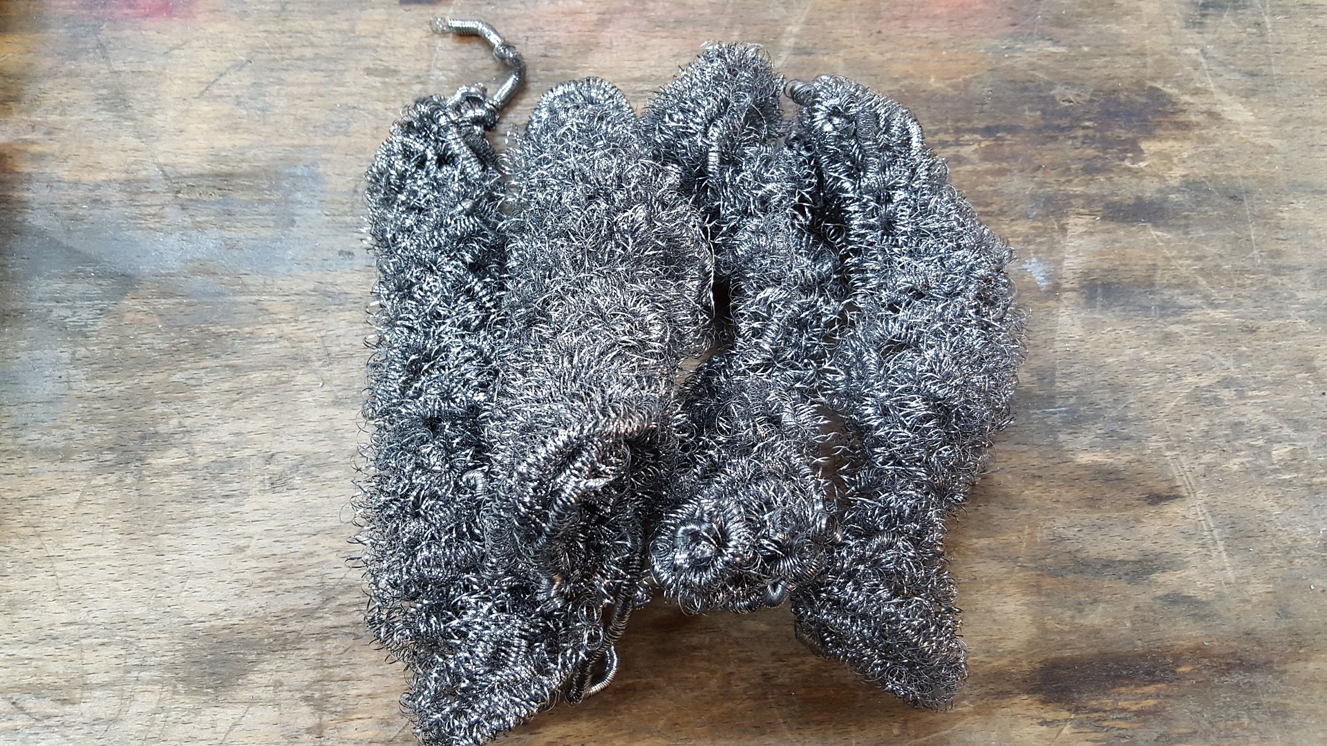
Stainless steel wool that I bought on the grocery store
Stuffed in the can
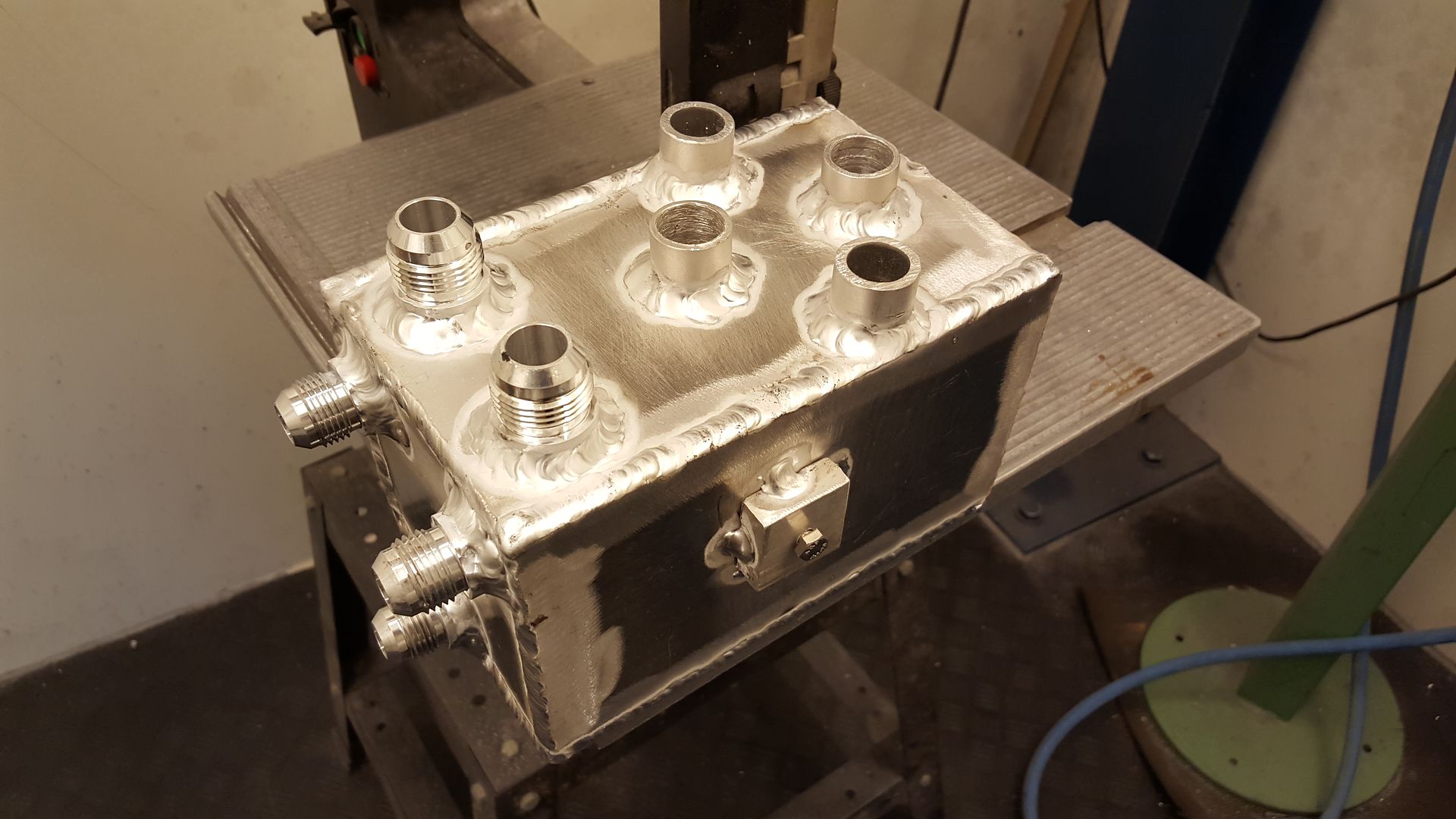
Aaaand DONE! About 5 working hours to make this can.
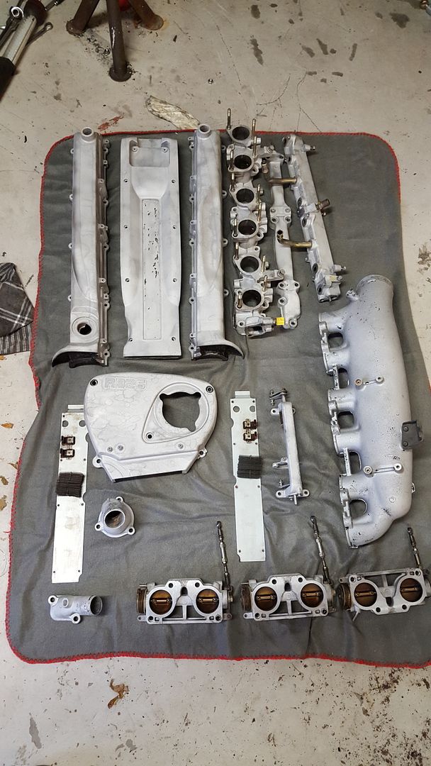
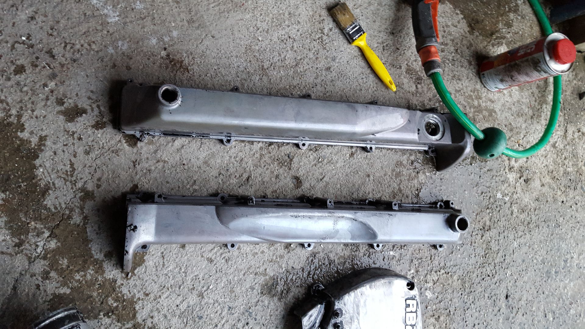
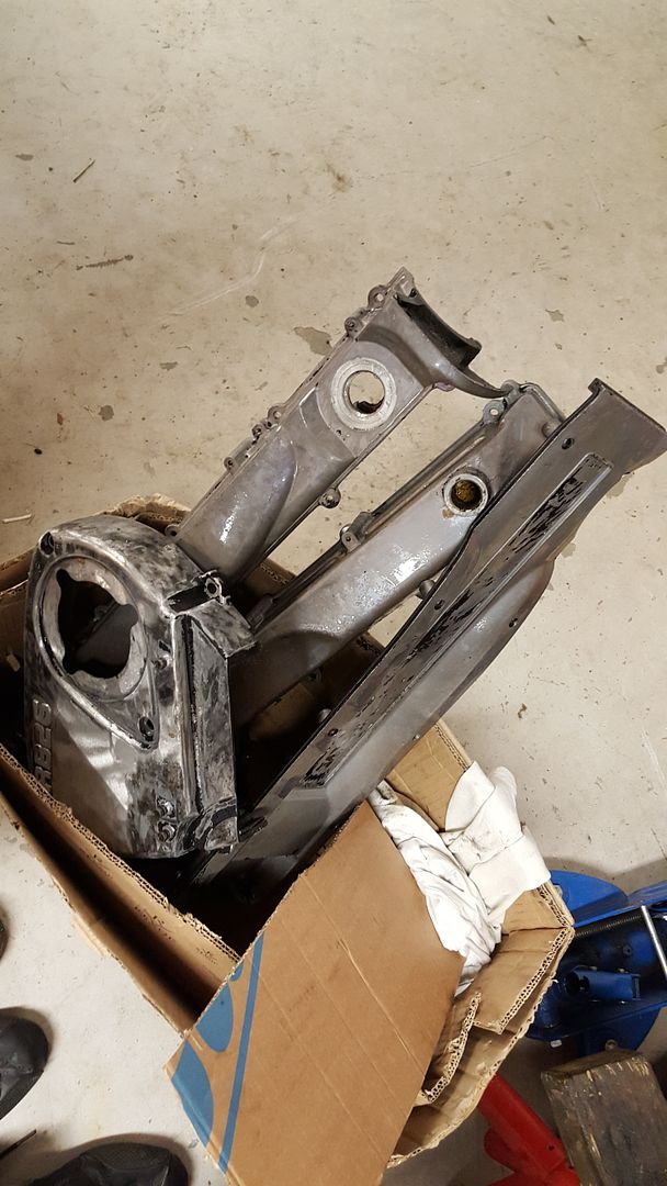
All the parts that is sandblasted and washed.
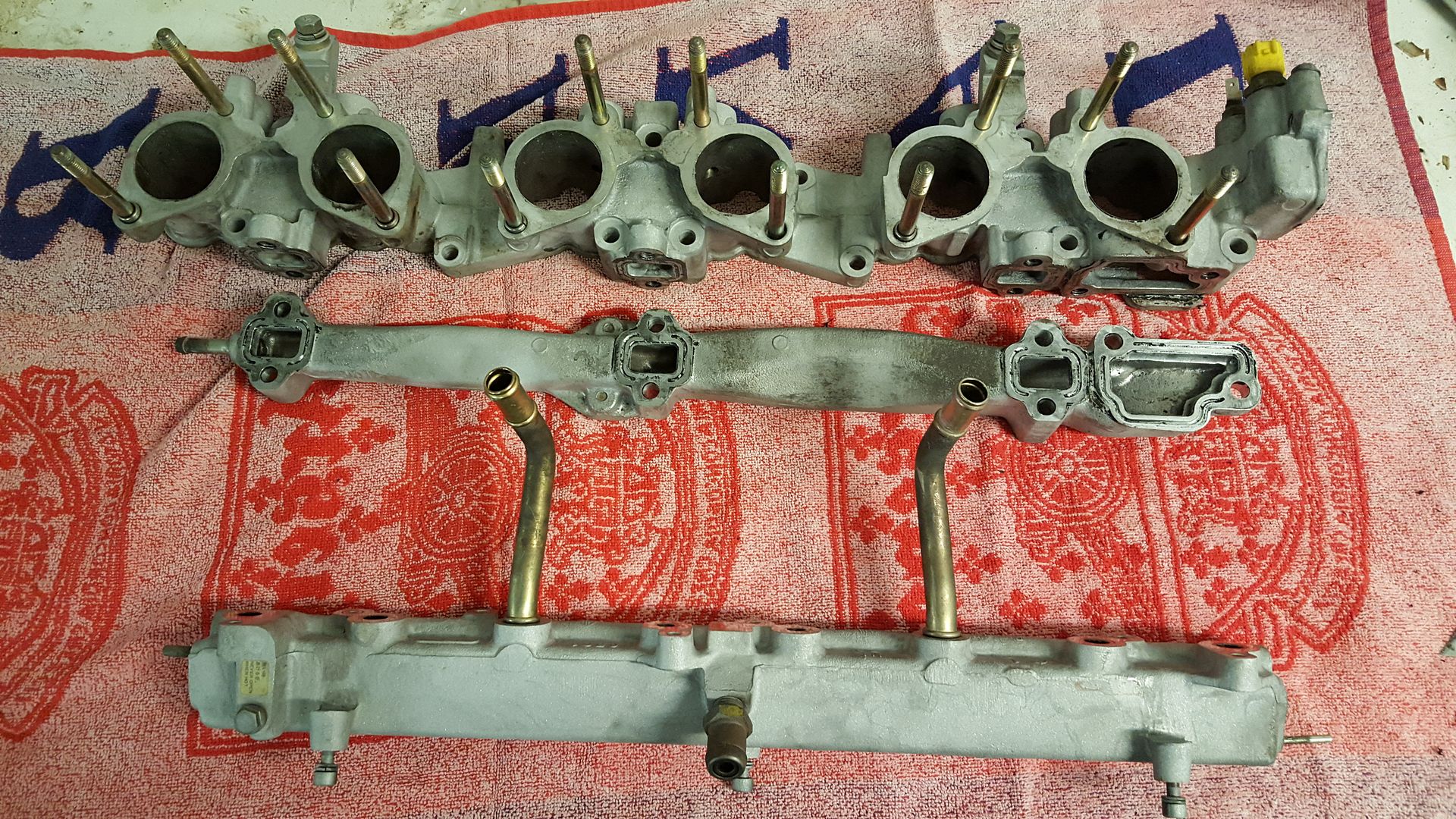
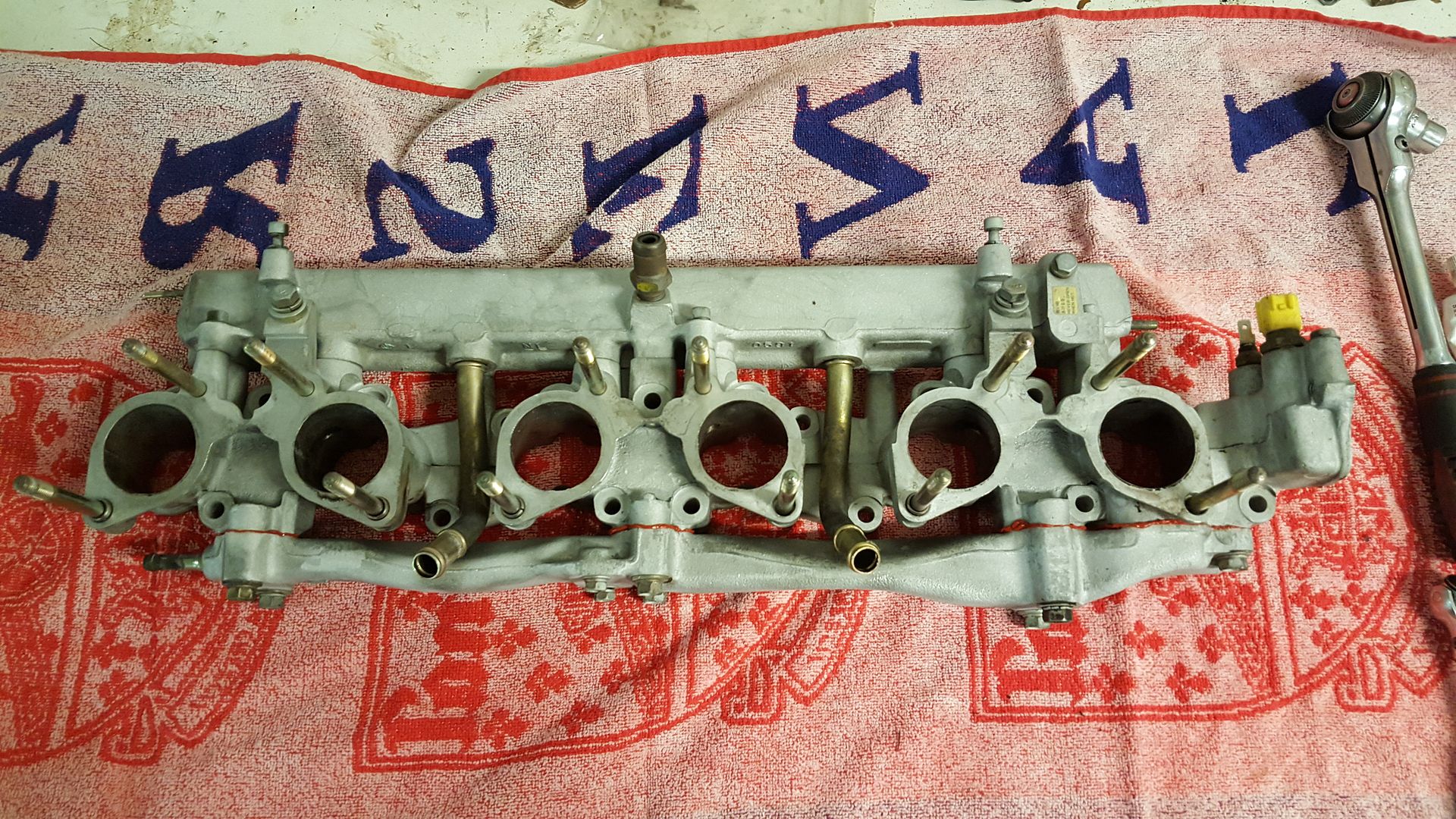
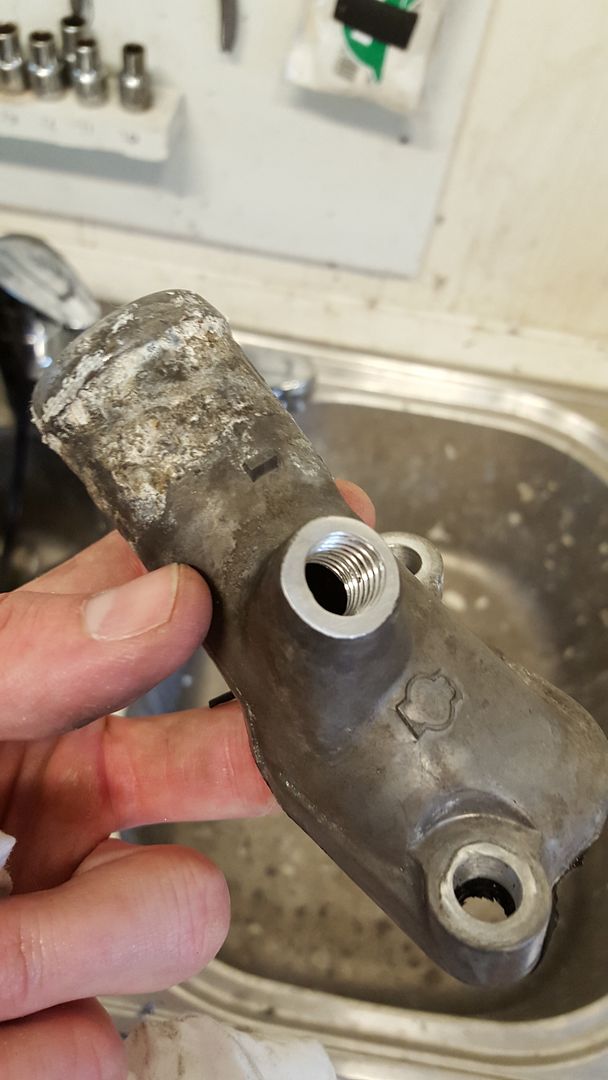
Assembly of the spacer between the throttle bodies and the head. I do not know what I should call this part. Carburettor maybe. On this part there is a vacuum rail and a water rail.
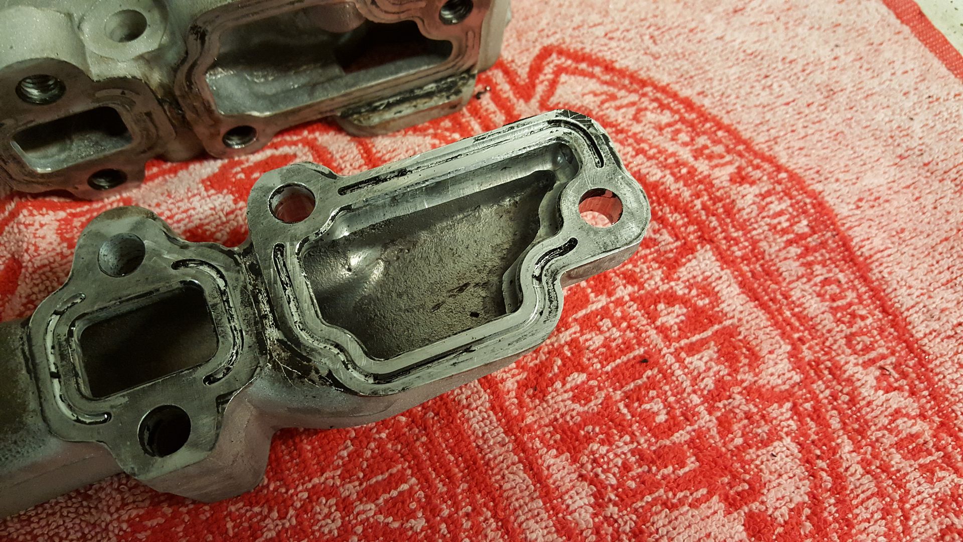
Scraped and cleaned the old silicone gasket
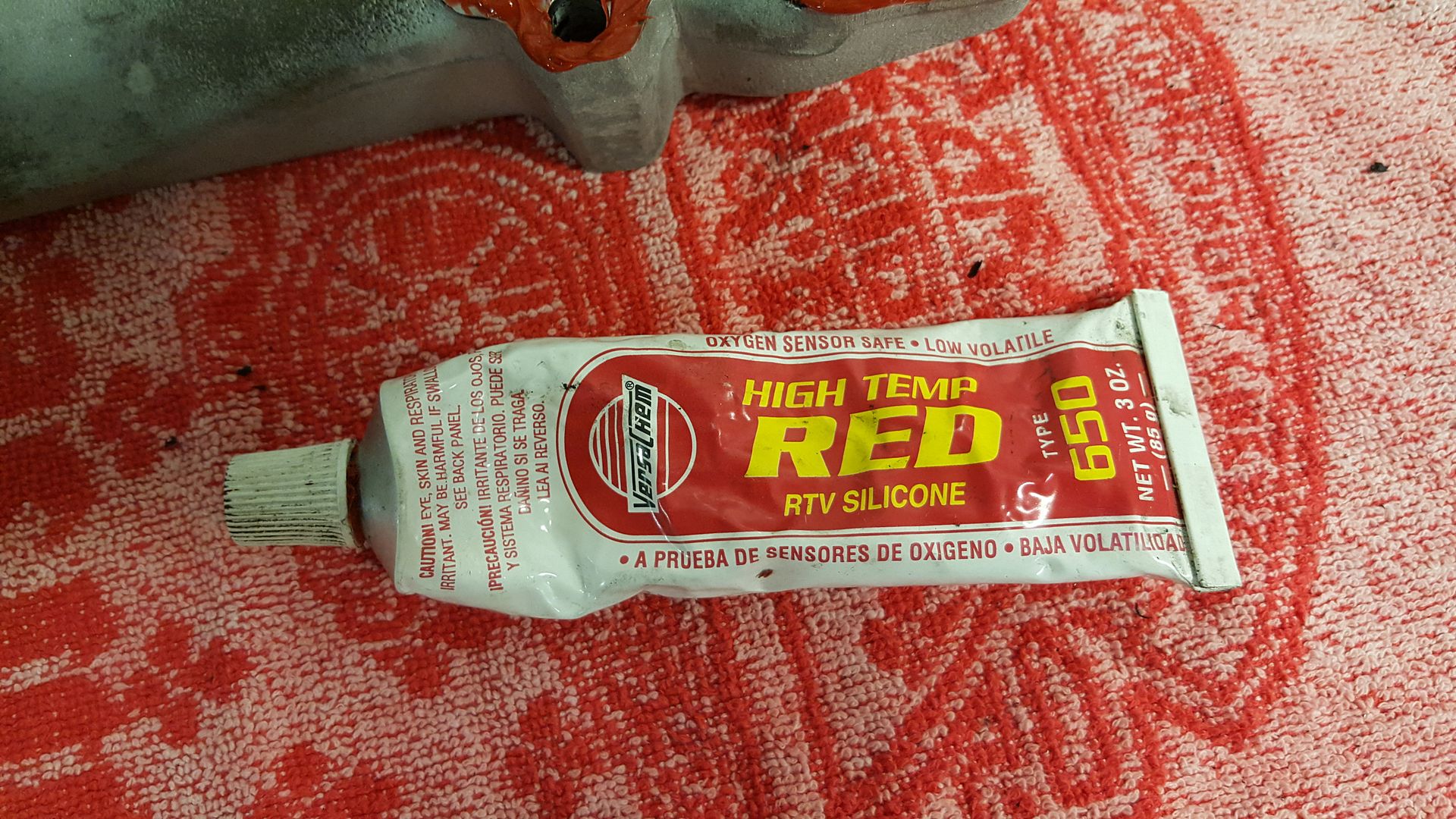
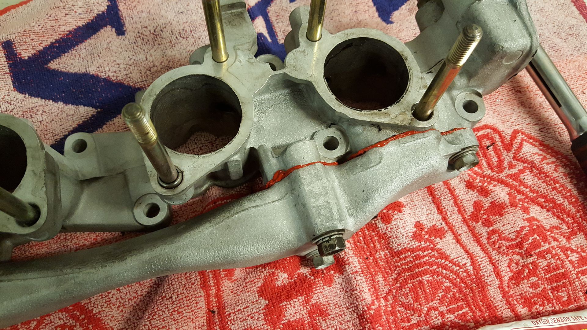
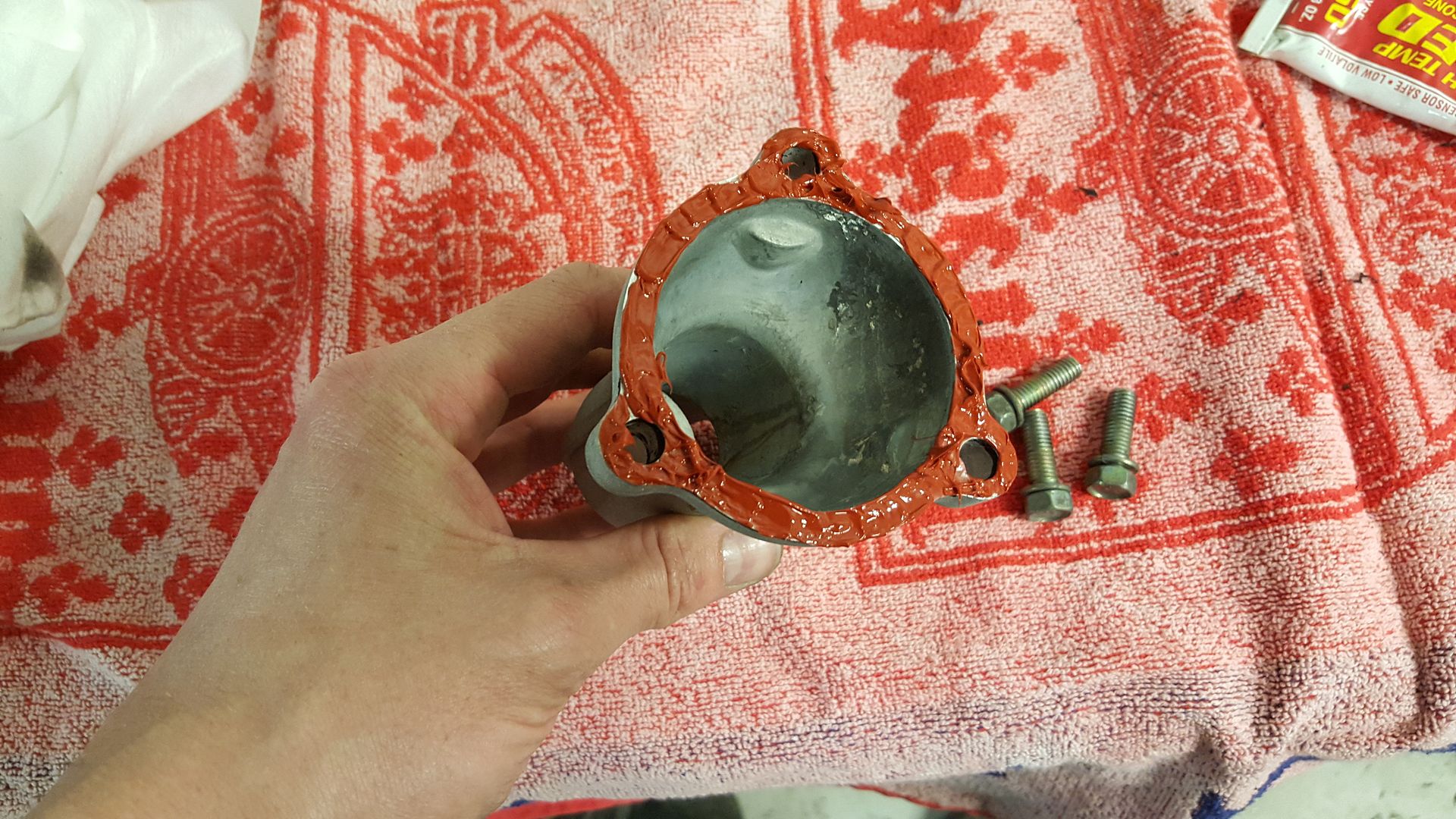
I use this RTV silicone for the job
Assembled
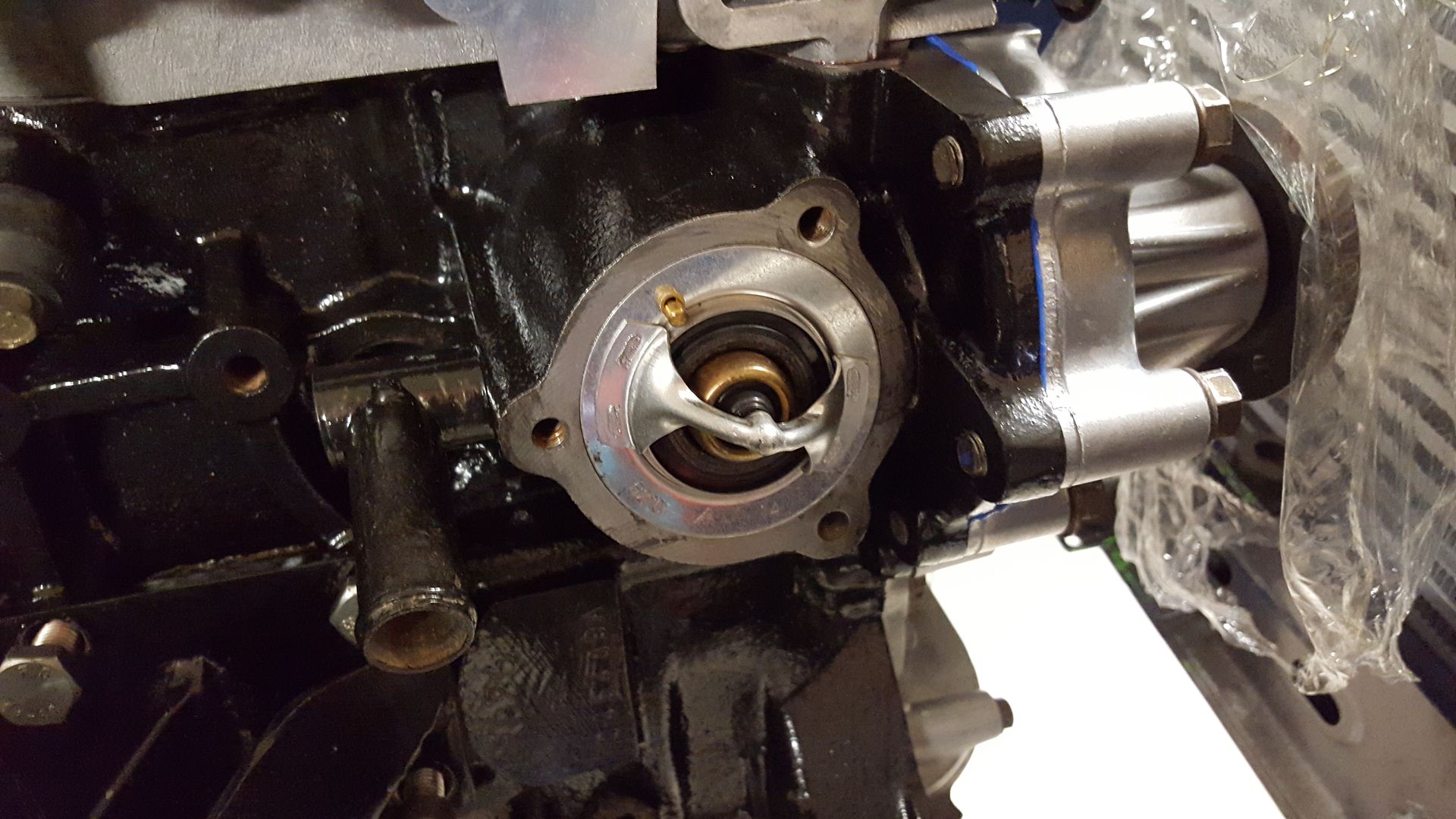
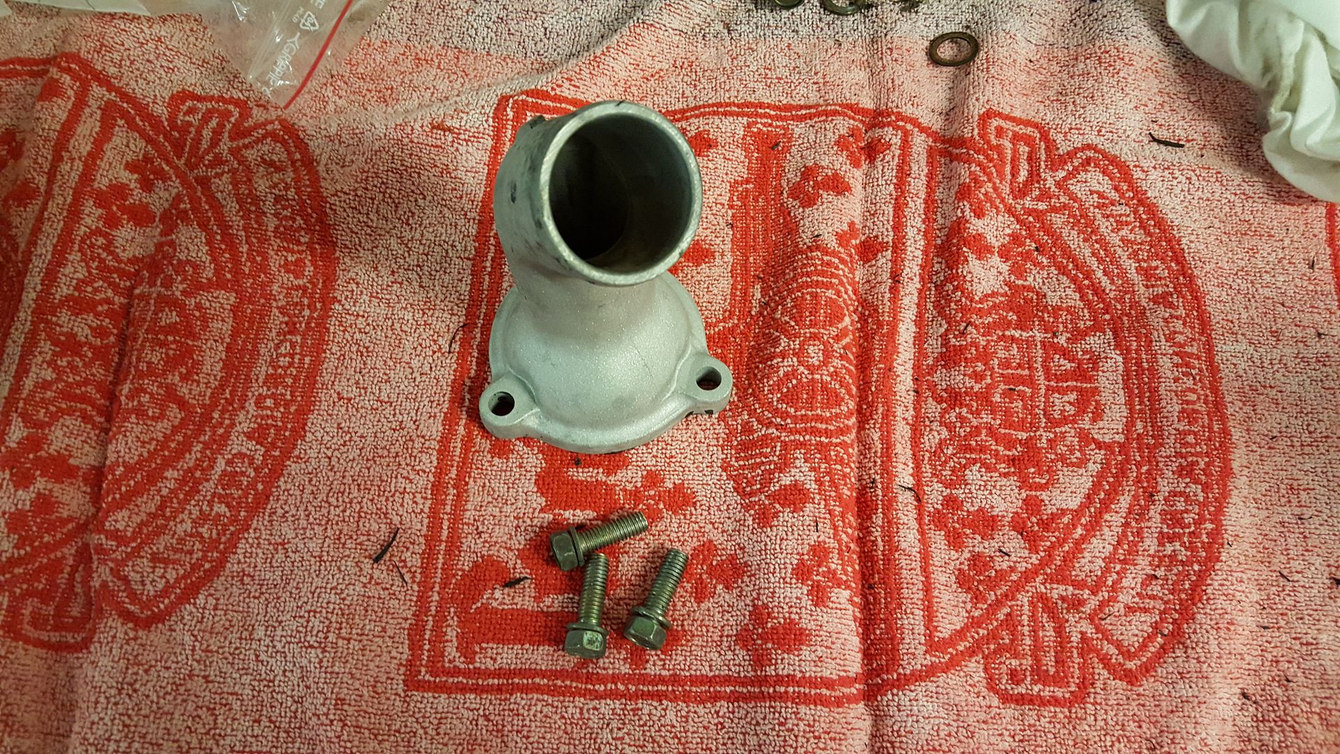
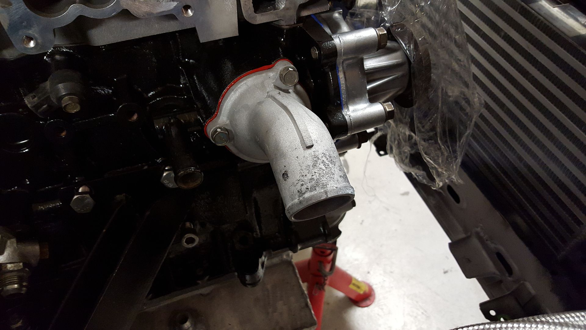
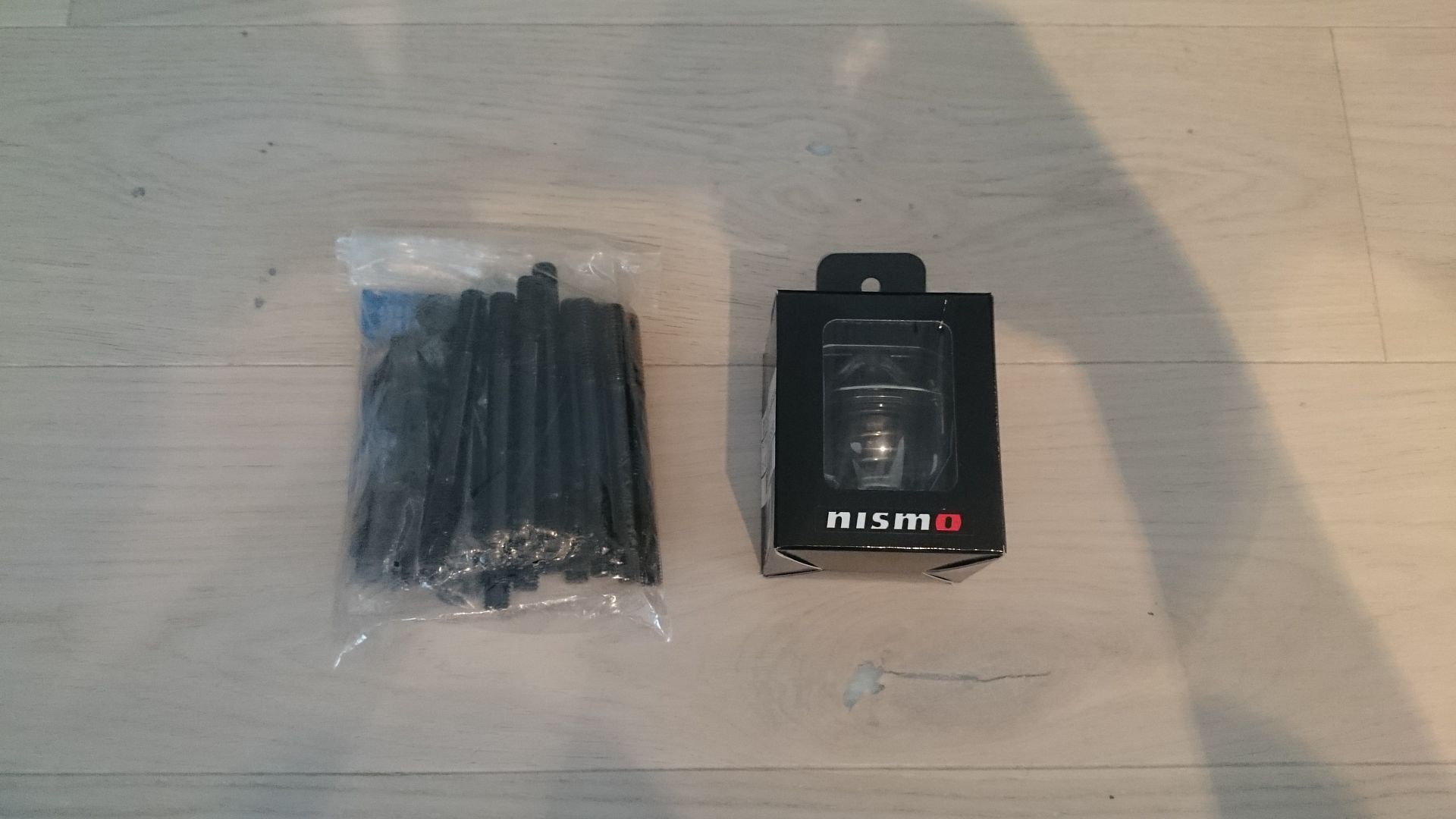
The NISMO thermostat was installed together with the thermostat housing.
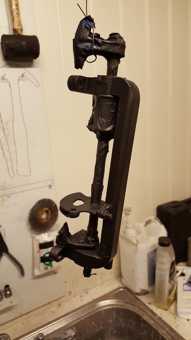
Painted the bracket for the throttle and throttle linkage black
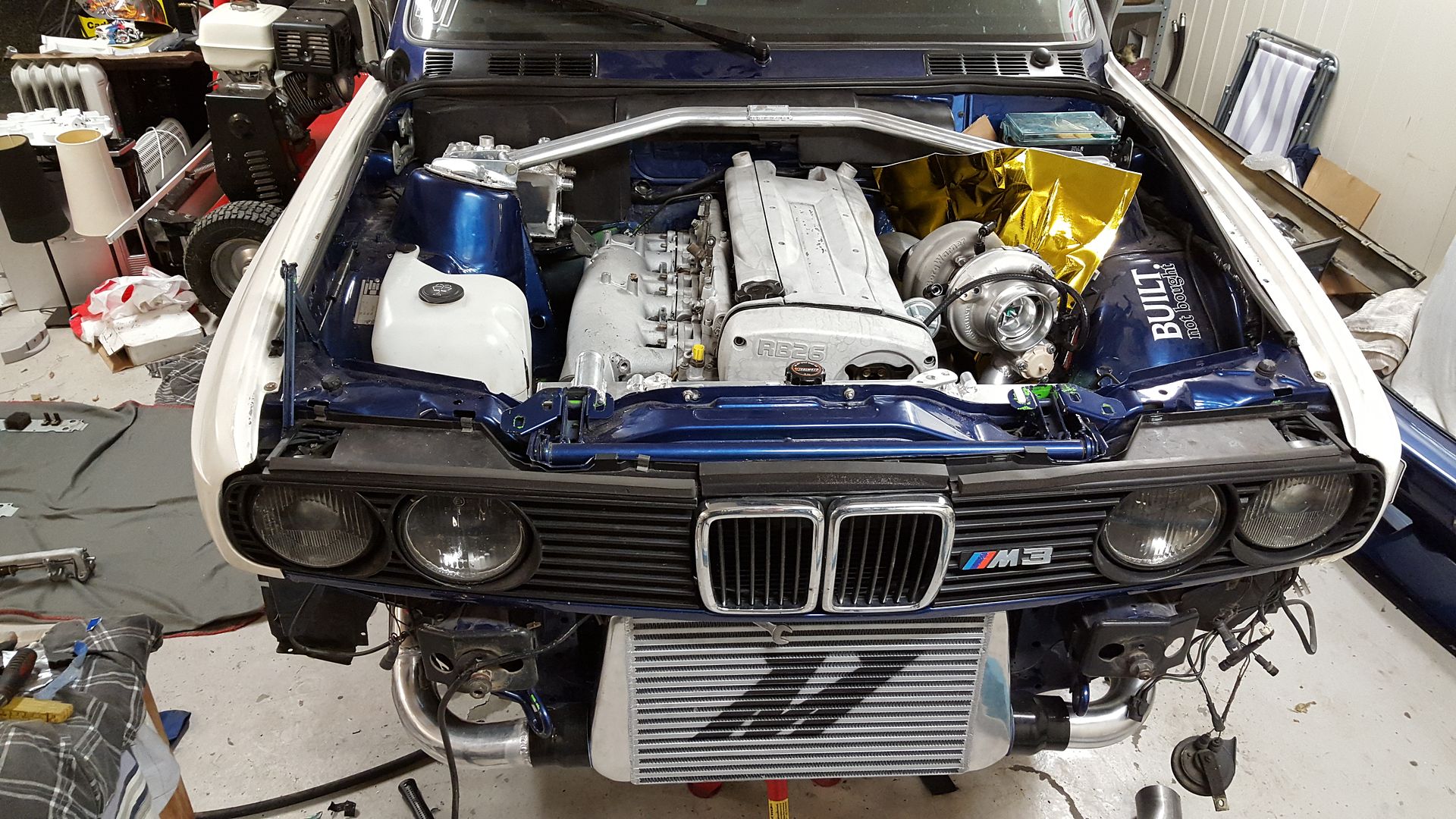
I just put some parts on the engine to see how it might look. I like this a lot!
-
2
-
-
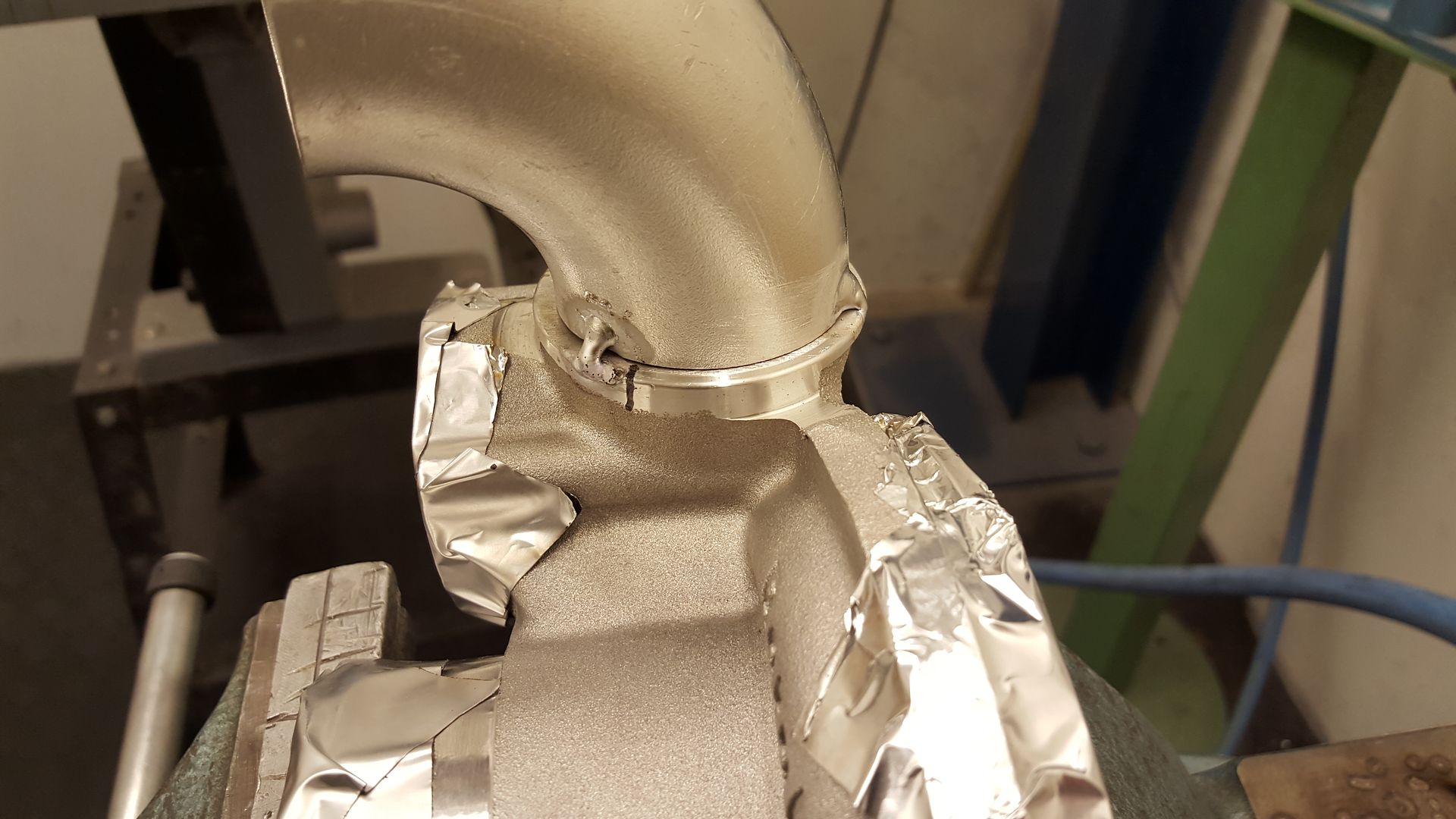
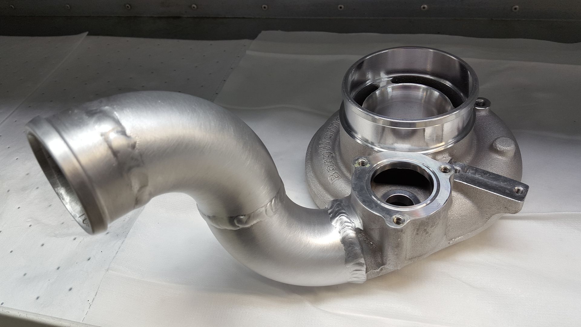
So, what have we done today? Yes, I have welded some more aluminium.
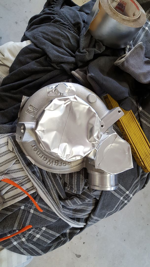
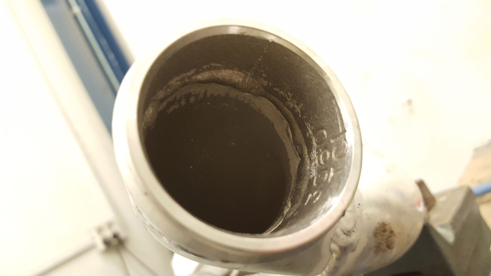
This time on that shitty expensive turbo.
Started off by removing the compressor housing
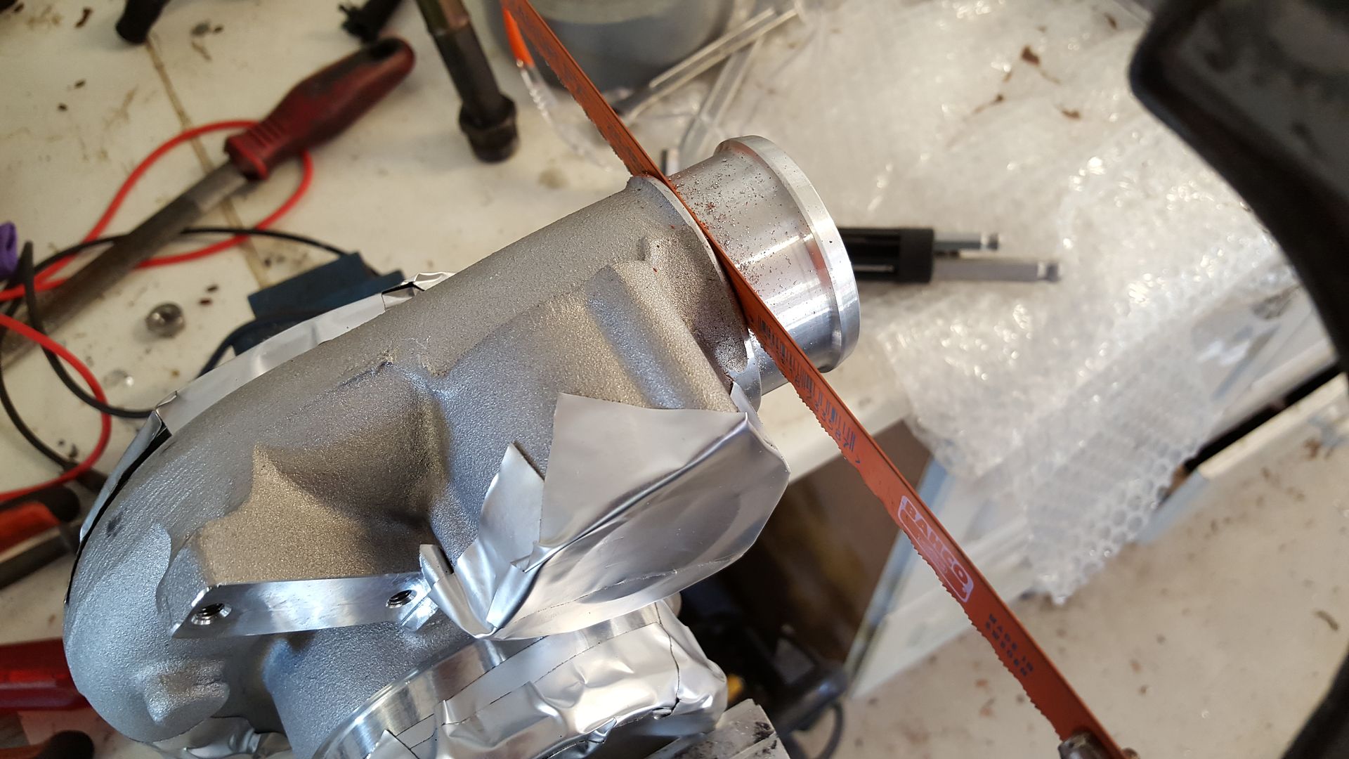
Then I masked it up with aluminium tape
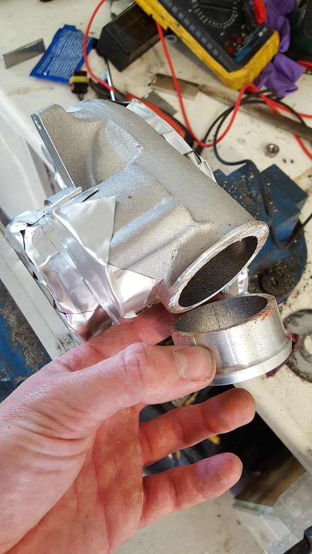
Cut it of with a hacksaw
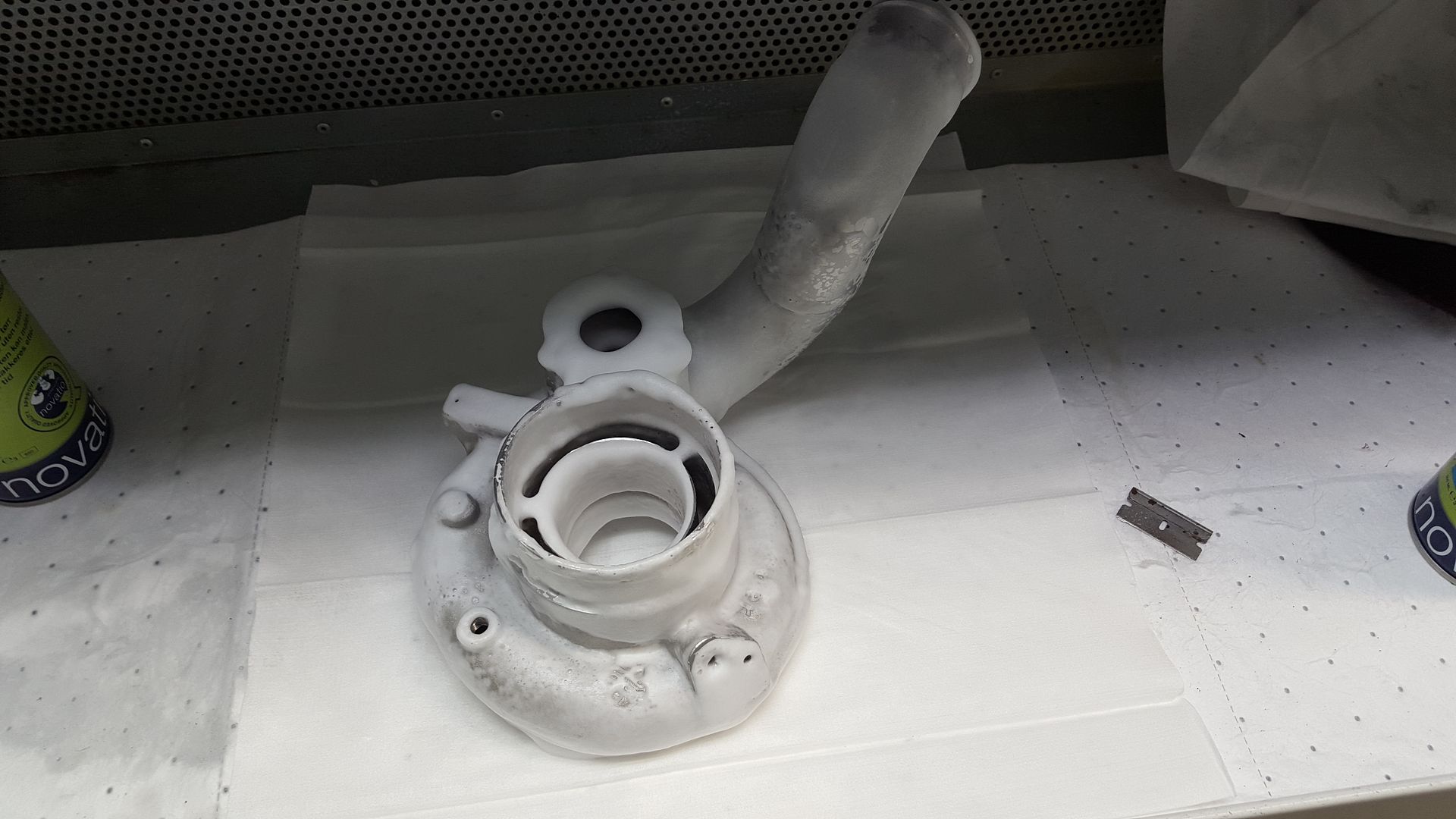
Drove over to my workplace and made it ready for welding
Spot welded
Work in progress
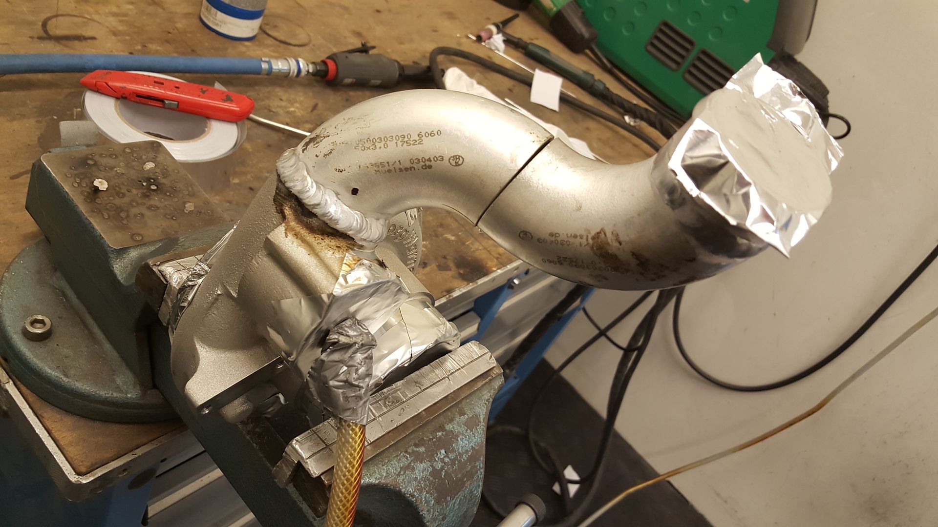
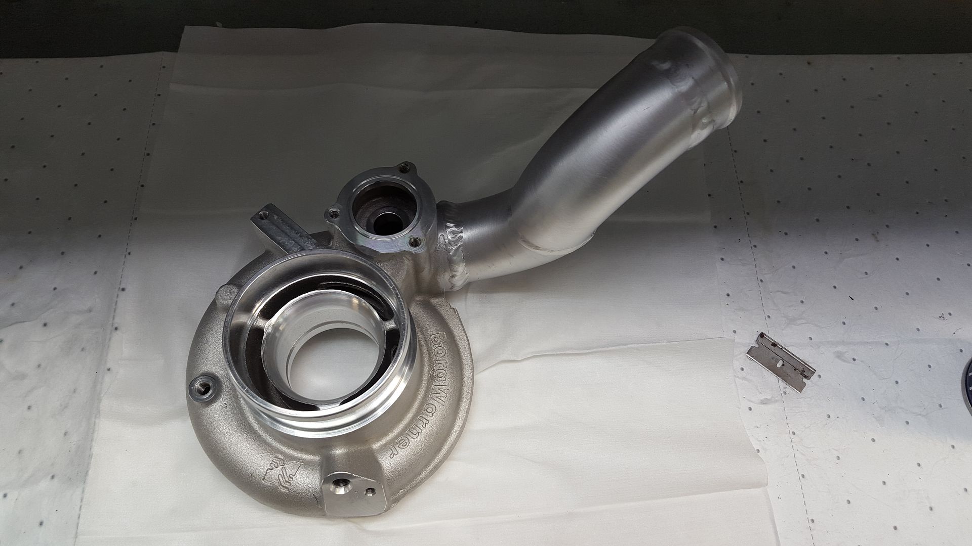
Done welding
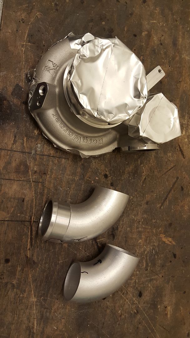
Used this weld as a reference for how much heat I should work with. So this needed to be match portet a bit.
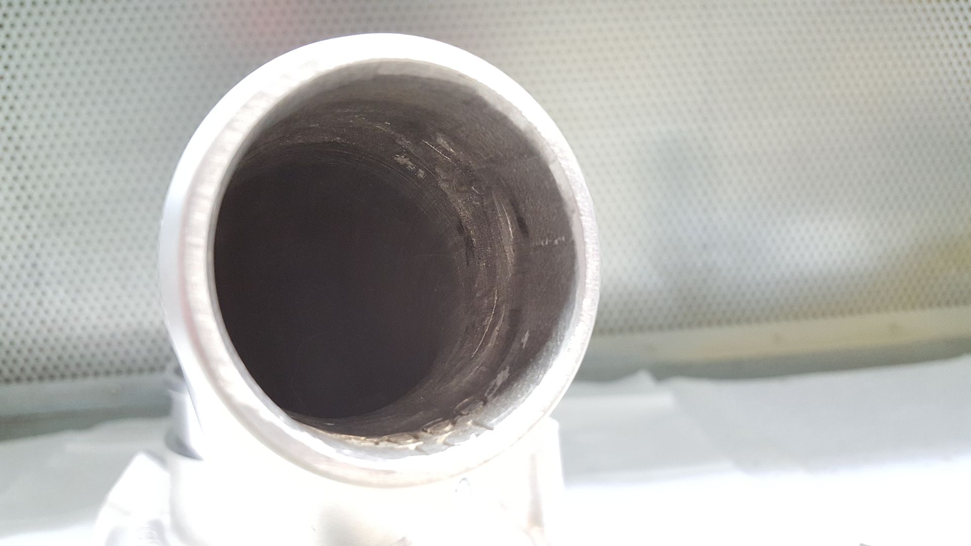
Ported and cleaned
I then sanded the pipes and finished off with some steel wool. Afer that I cleaned the hell out of it!
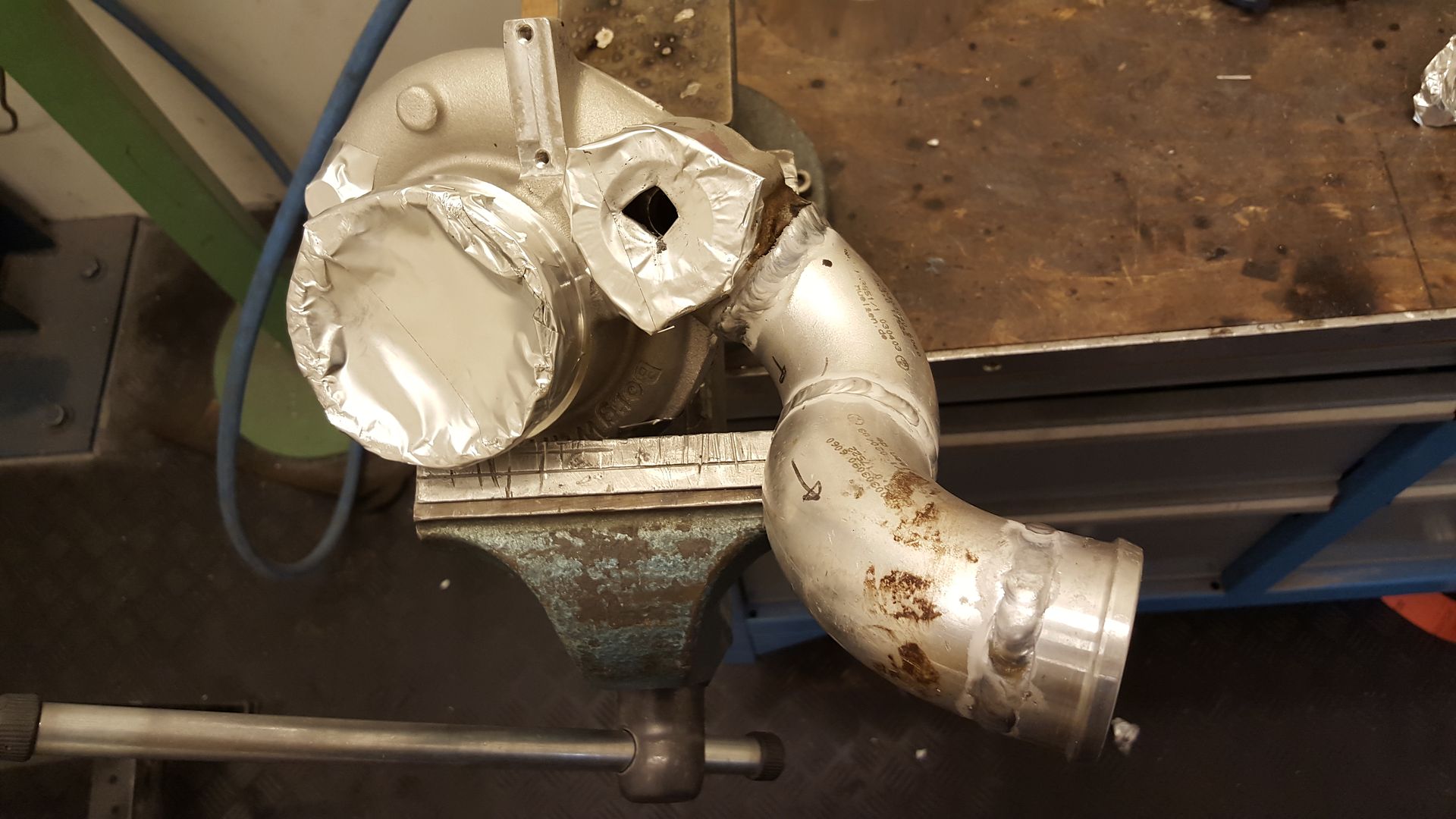
Final product
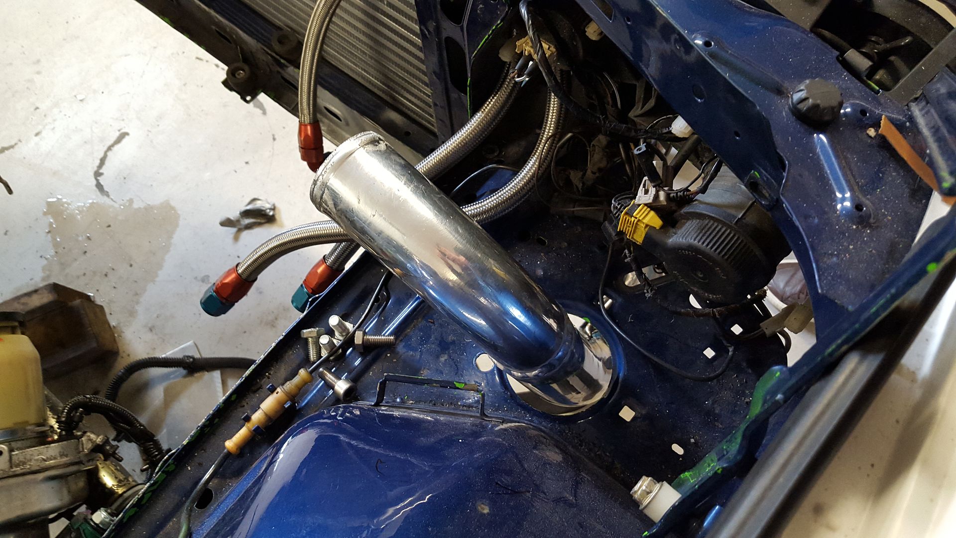
And I had to test it in the car before bedtime!
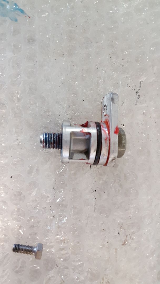
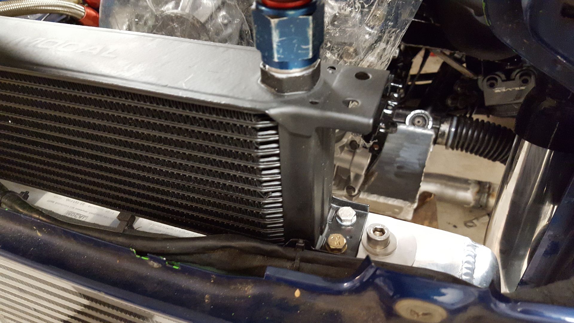
Also bolted up the oil cooler. Did not have more left of the clear bolts, so I had to use an anodized one. This bothers me, so I have to buy some more bolts so they can all be the same.
-
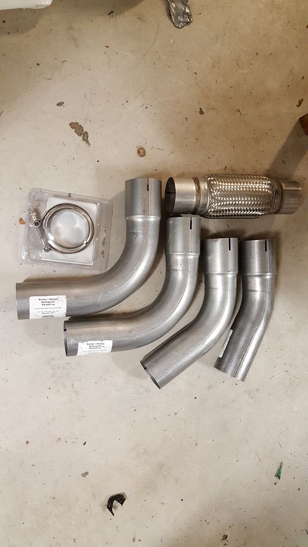
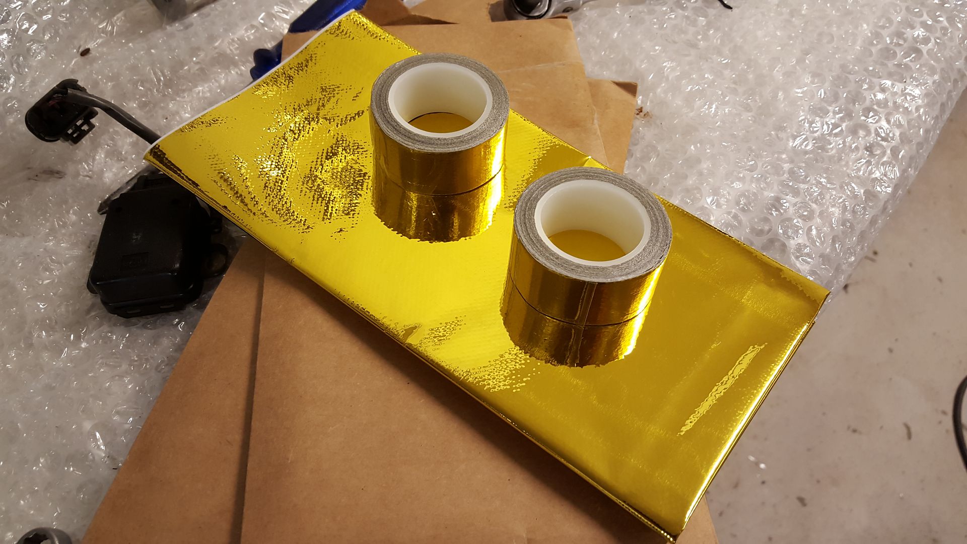
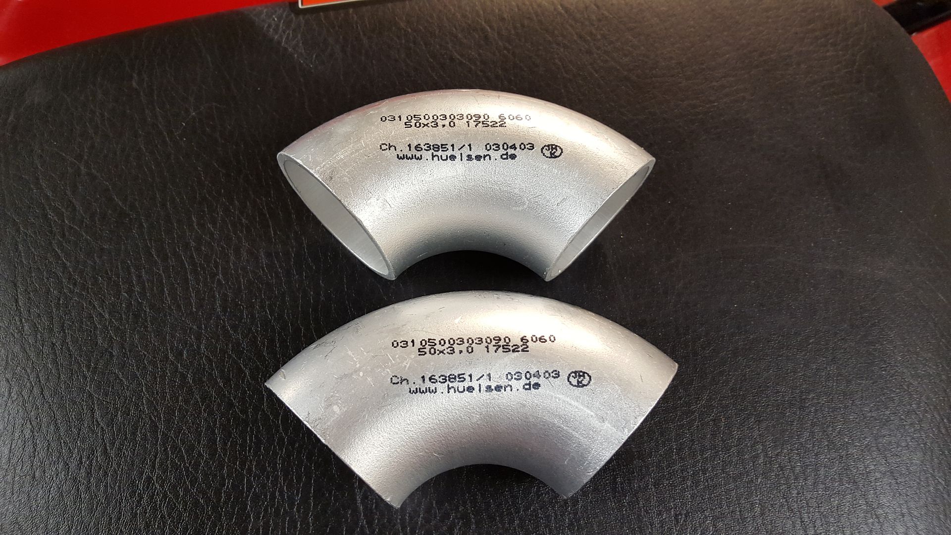
Did get some more things sorted. Have sand blasted the things that is going to be paintet, got hold of some parts for the exhaust, aluminium bits to weld on the turbo and gold heat foil.
-
Could not resist. So I went out for another hour or so in the garage tonight.
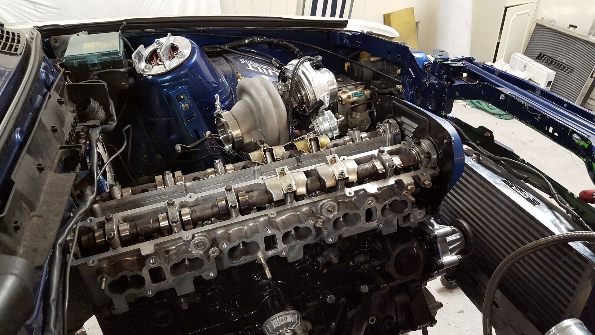
It is in. There was not much room for the manifold. Guess this was just luck!!
-
I have not made that great progress today, since I had to spend some time on Ebay to source some fittings that I have forgotten to order. Damn. I was hoping that I had ordered ALL the fittings.
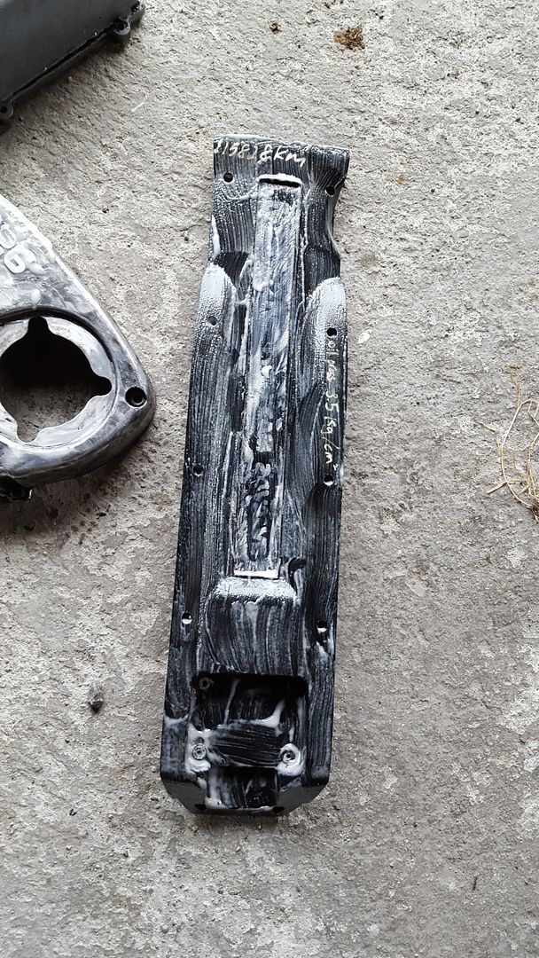
I want to dress up the engine, but have not decided on the looks yet. I'm leaning towards black wrinkle like the S50. Regardless, the old paint needed to go. So I went on with some paint remover.
Mounted the fittings on the turbo
In order to get a nice line for the water return from the turbo, I decided to thread the top line from the radiator. I will put in AN6 adaptor here.
Cut it off...
Drilled out
Thread
And done
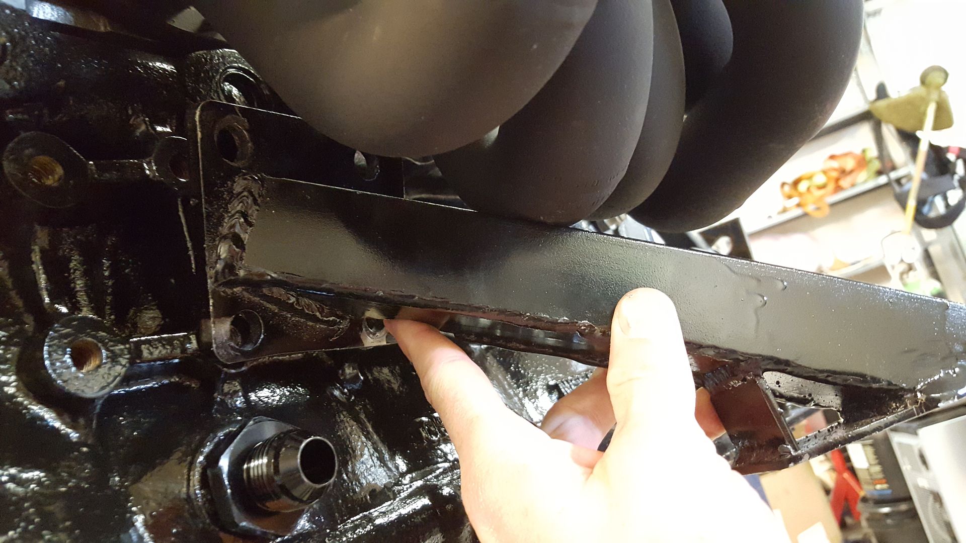
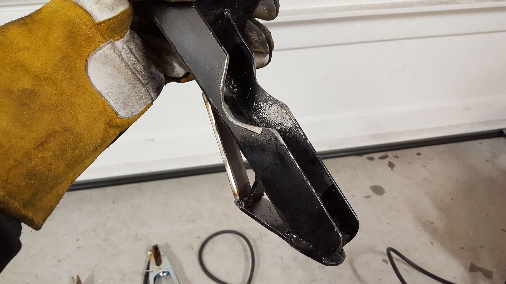
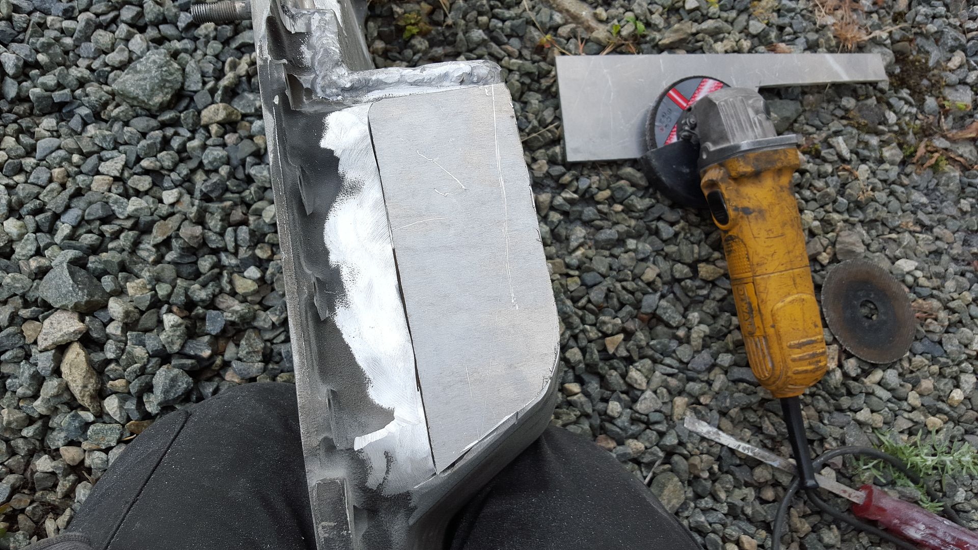
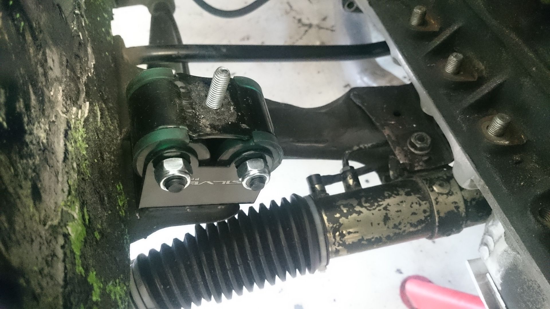
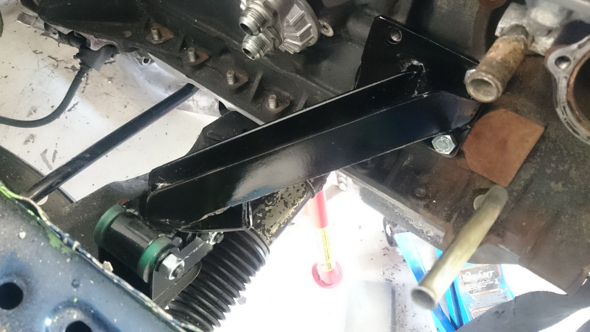
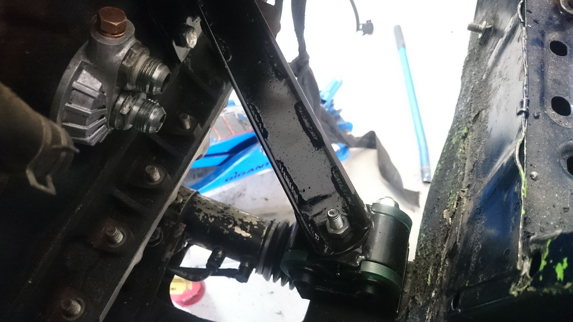
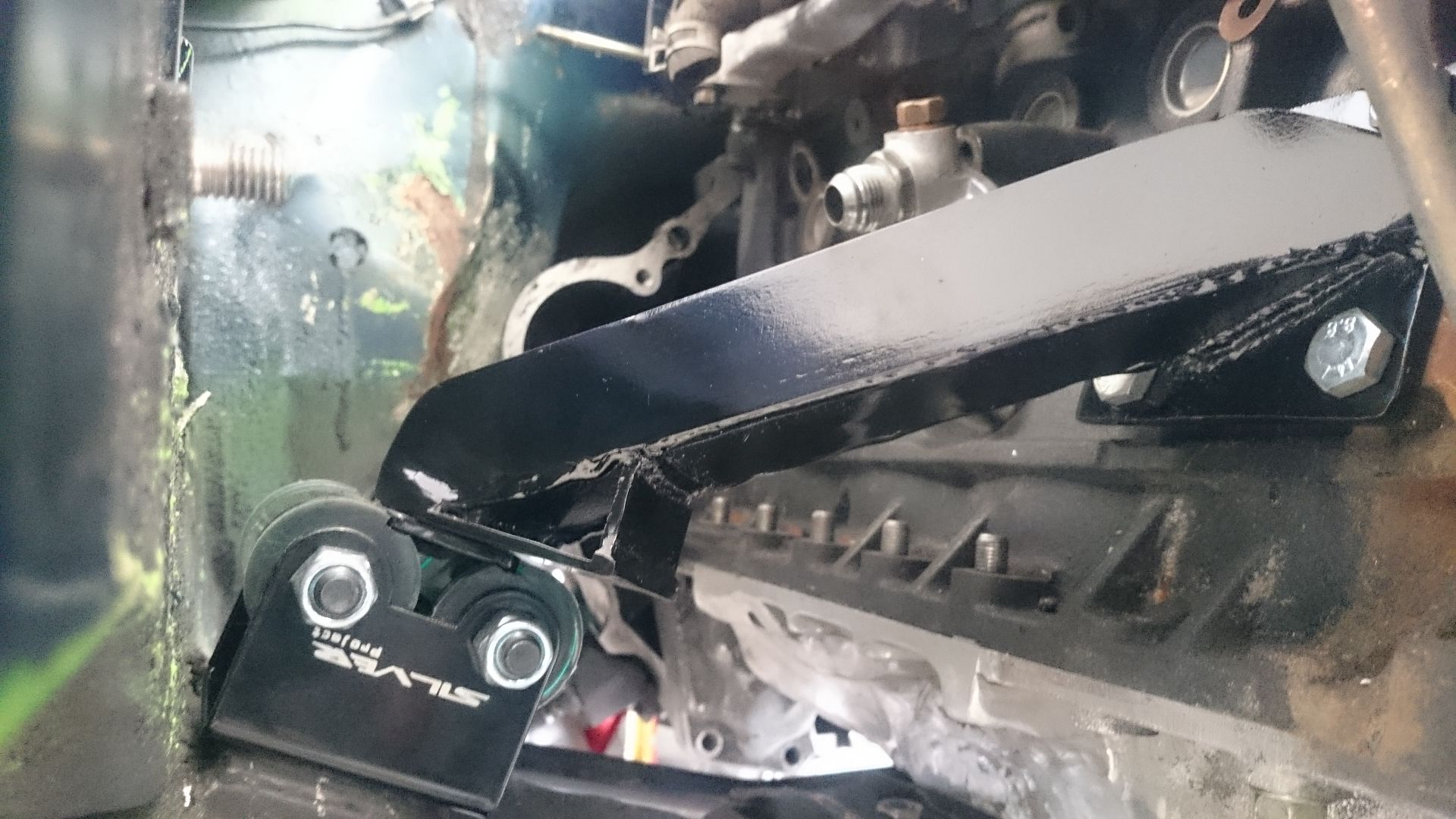
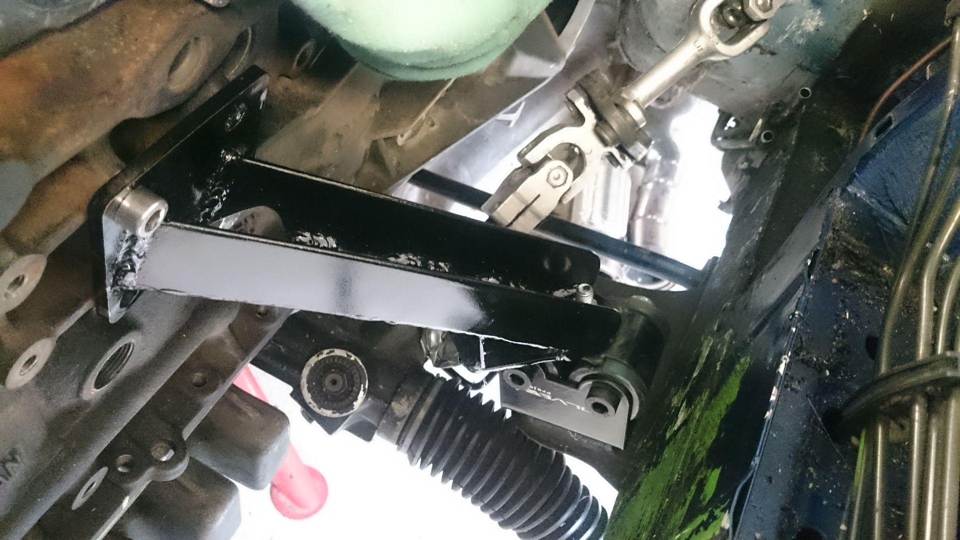
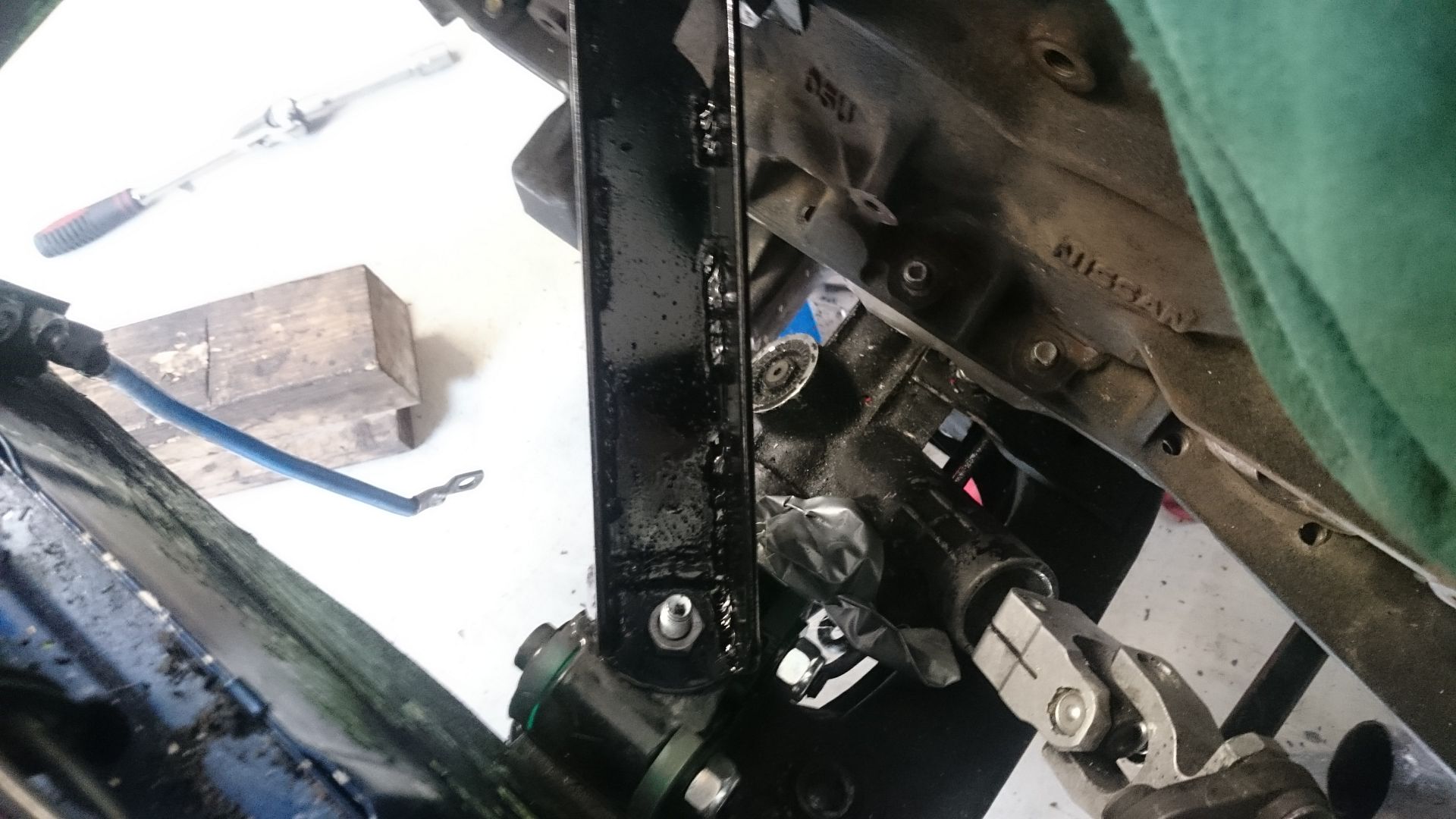
I buildt the engine mounts way before I got the manifold, and they needed to be modified.
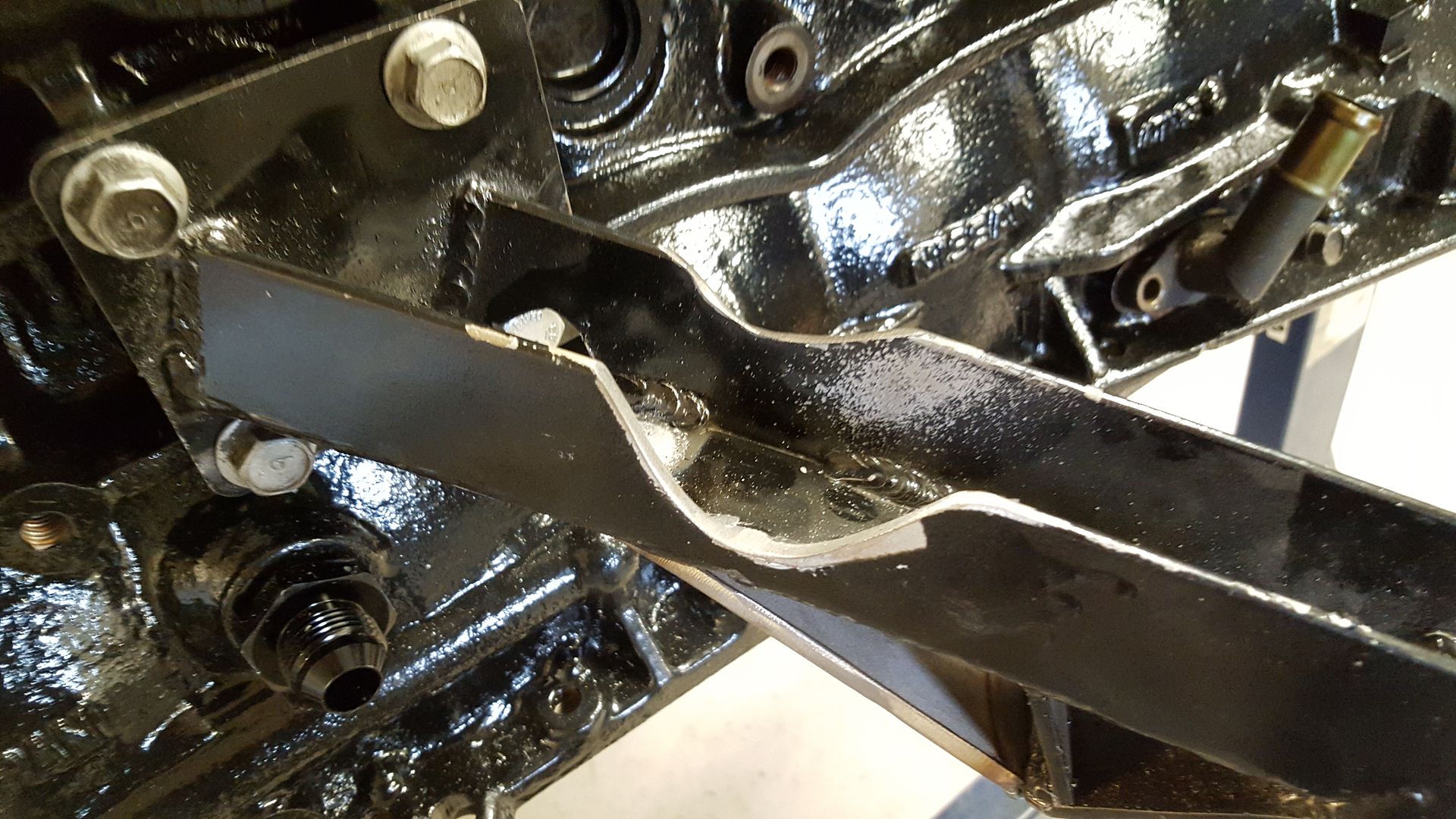
Like this, I also reinforced that one on the uderside to be sure.
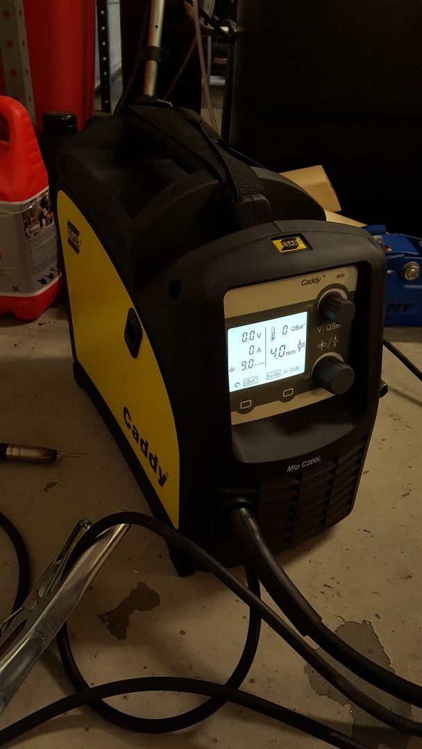
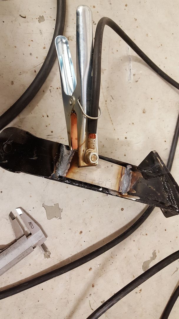
To do that I used my new ESAB Caddy C200i MIG welder. Just bought this baby couple of moths ago, and I can't understand how I managed to work on this car without my own welder before.
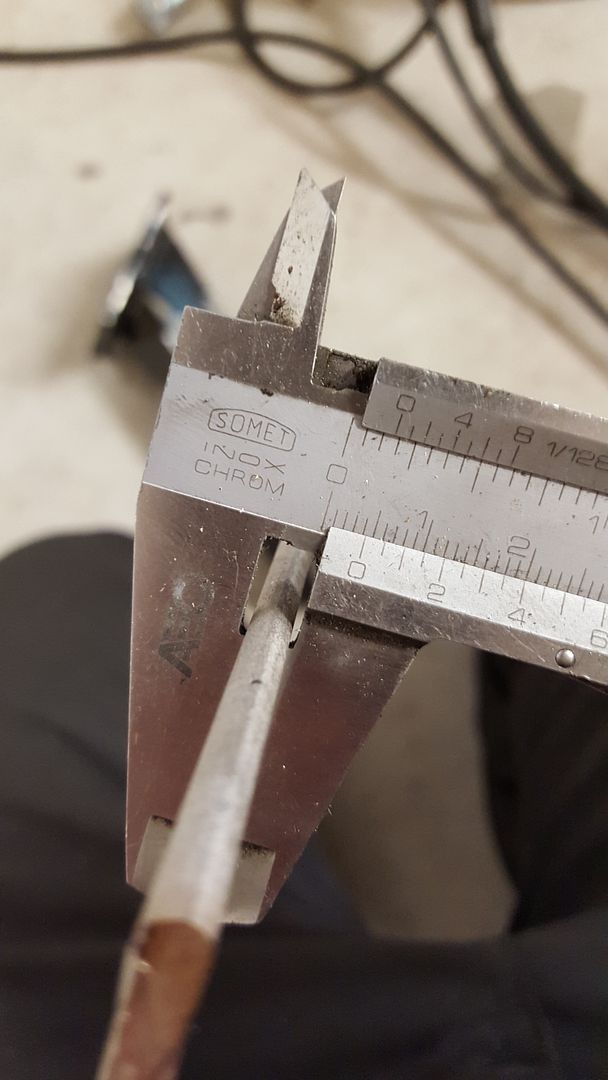
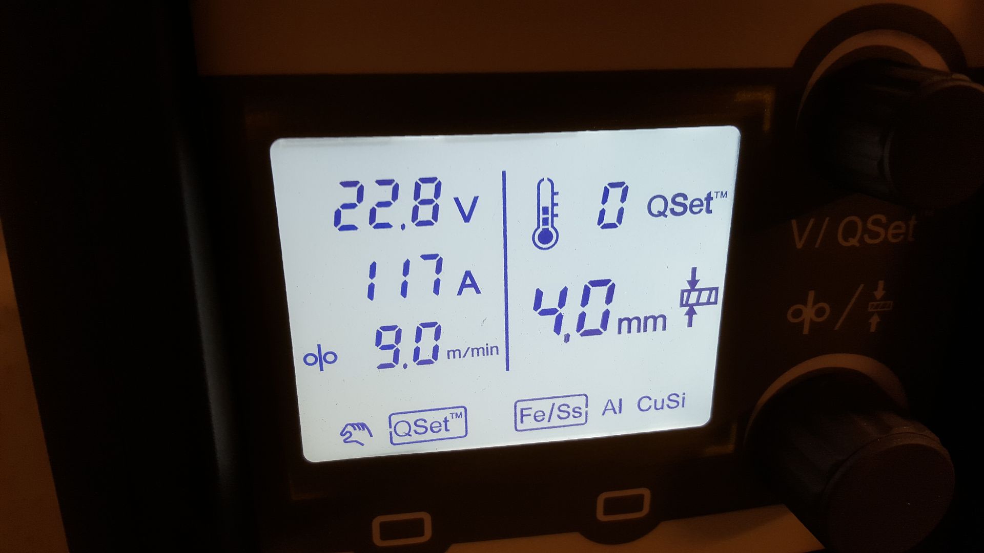
Here is a little instruction on how it works. First off you measure the material you are welding. In this case we have 4mm stainless steel.
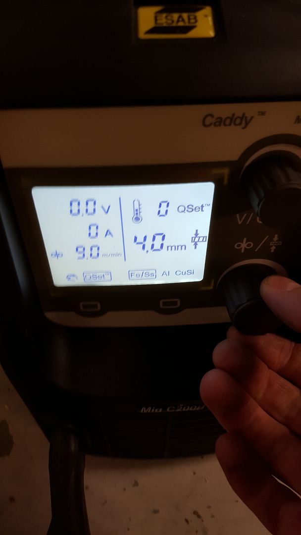
Then you just select 4mm on the machine
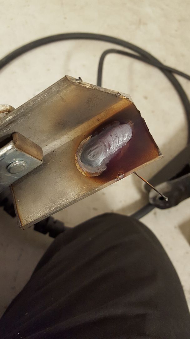
Weld for a few seconds on some equal steel
And the machine have set itself for the optimal setting for that weld. Easy!
And done!
I bought ARP manifold studs for this, so I removed the stock ones today and mounted the ARP one. I think this actually made quite a difference in the looks as well.
Old ones...
ARP mounted with the manifold
Some random overview shots (before ARP)
-
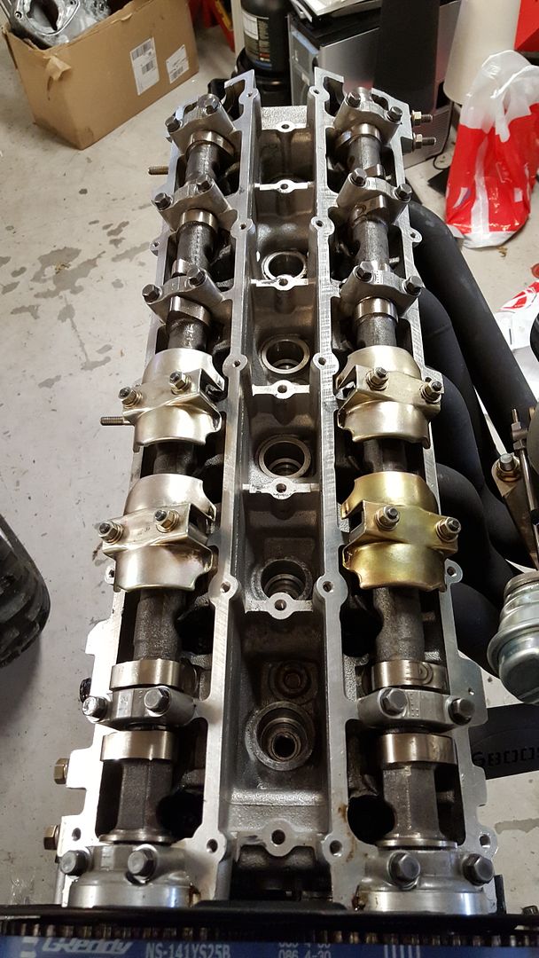
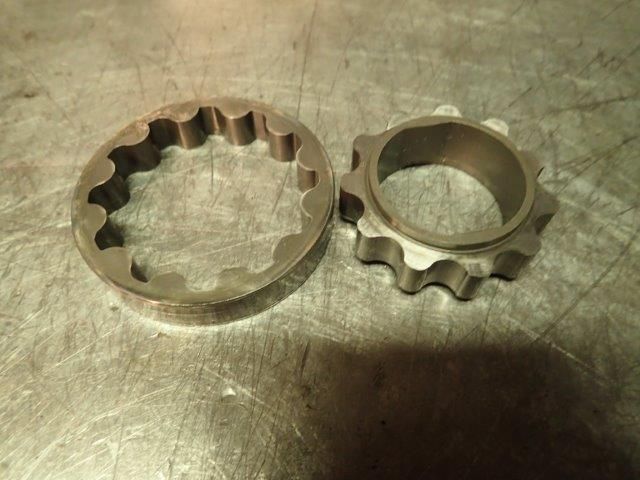
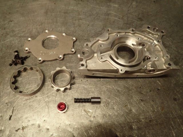
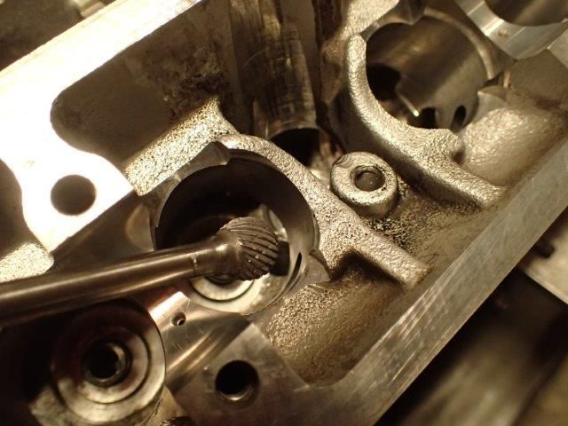
The gears was dry. No type of grease or lube on them. That would tear a lot when you are starting the engine for the first time.
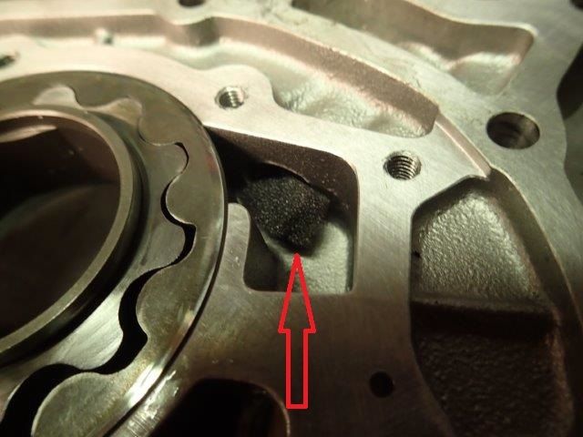
Here you can see sharp edges and no smooth machining. This is not good for oil flow.
The same ports after some porting an polishing
Cleaned and ready for assembly
He put on some special grease on the gears
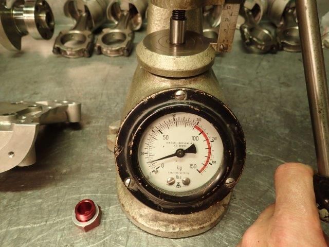
Checked the pressure preload on the spring
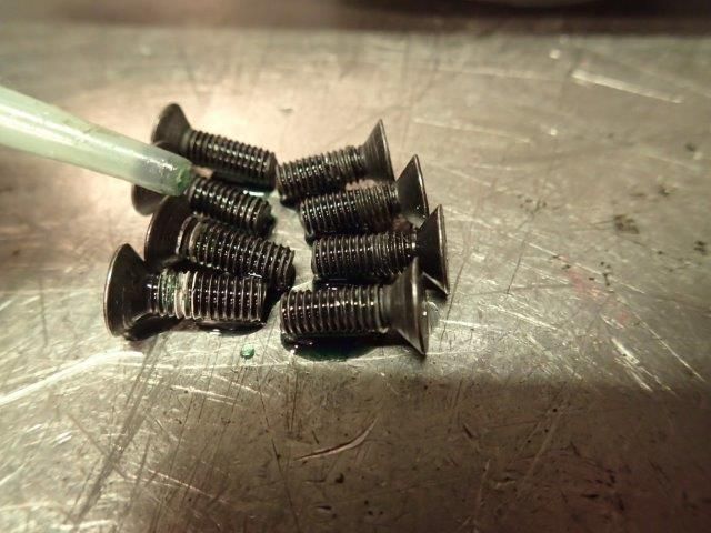
Loctite on the bolts
Done and done
As I mentioned I picked up the engine yesterday. I was home late, so I only took some quick photos.
-
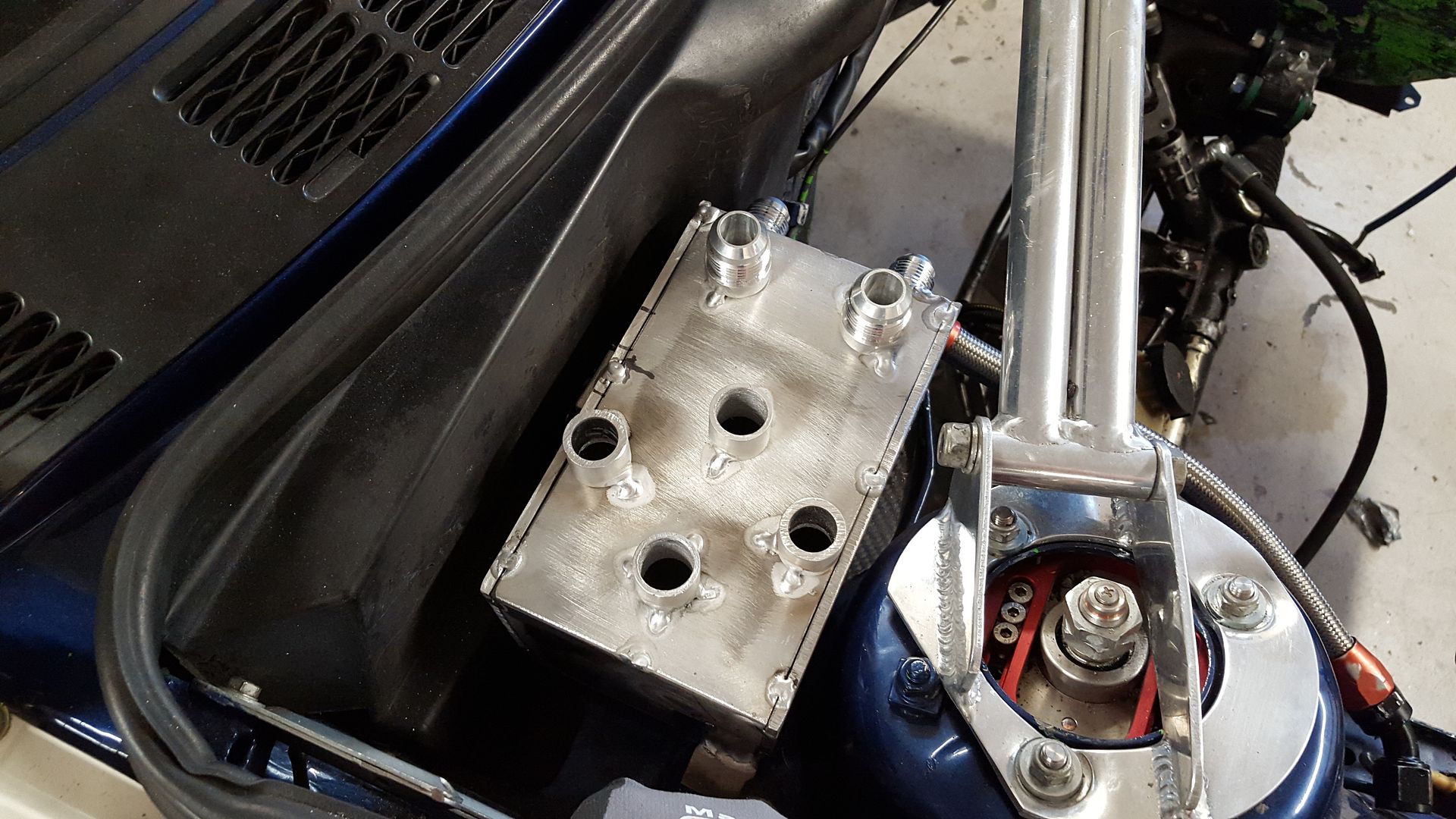
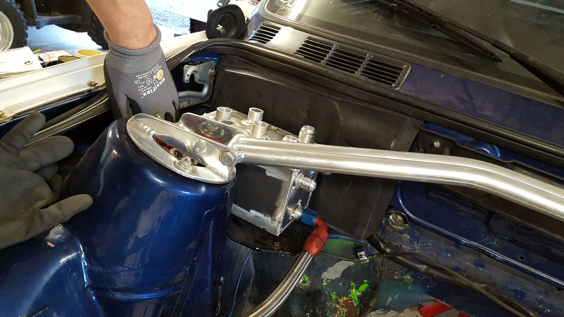
I then took the box to test in the car, and I had to modify it a bit in one corner. So I ended up with this as the final result
And this will sit in the car where the stock coolant expansion tank is placed in the M3.
Another story is the engine. I picked it up yesterday from the engine builder and he has put down a lot of high quality man hours.
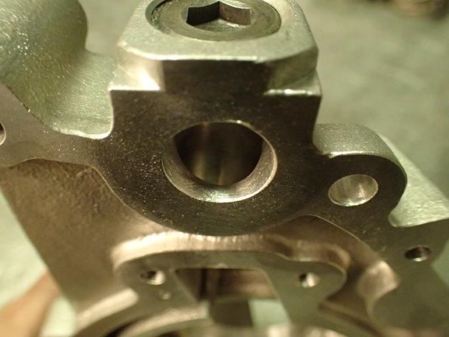
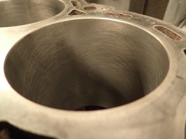
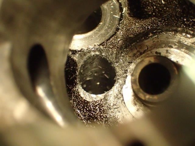
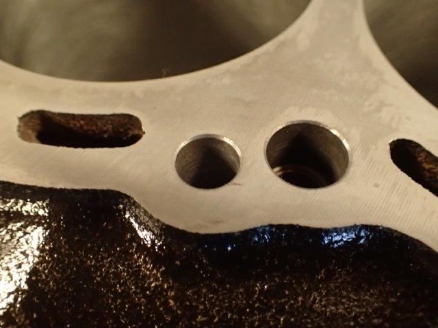
Since the RB26 suffers from a crap oil system, there is some work that can be done to make it better. One of those things is drill the oil return galleries bigger to match the head gasket. The main problem of the RB26's oil system is that when you push it hard it fills the head with oil. That results in a dry sump, the type of dry sump you don't want. And we all know what will happen then...
So, I got some photos from the builder on the job he did with my block and head. He will send me photos for the rest of the build later.
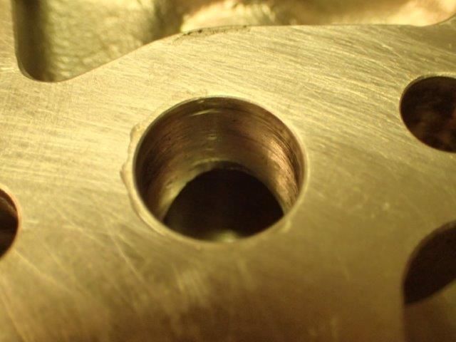
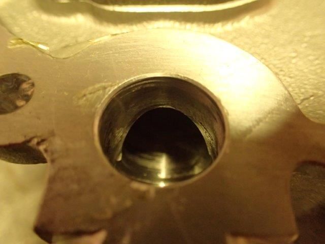
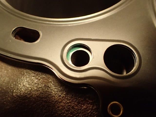
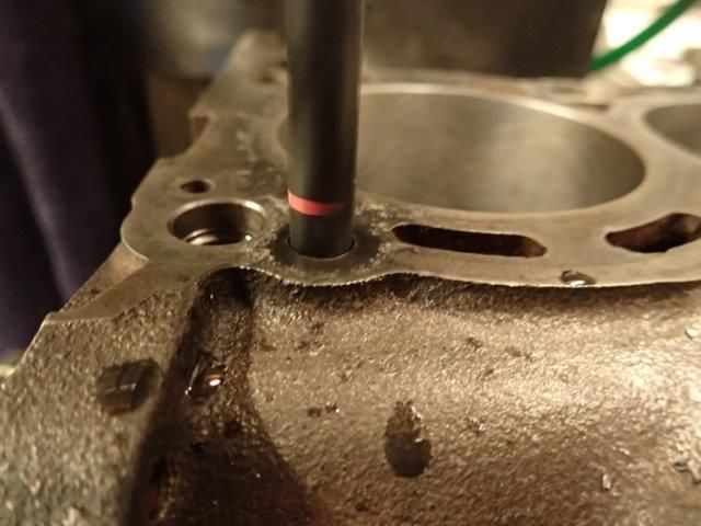
First he pressure tested and honed the block. Then he put it in the jig to drill the return holes.
The holes for the return galleries can be seen here
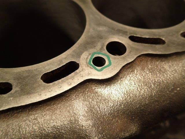
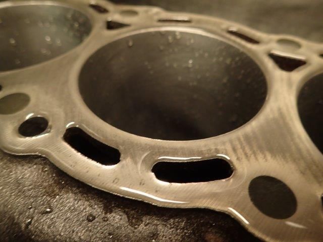
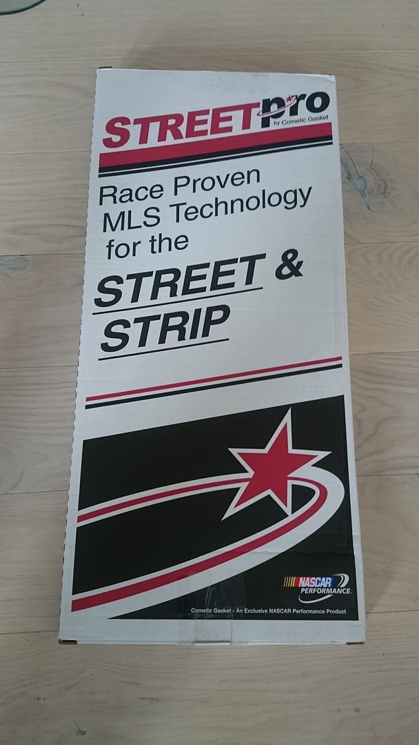
Here with the Cometic MLS head gasket
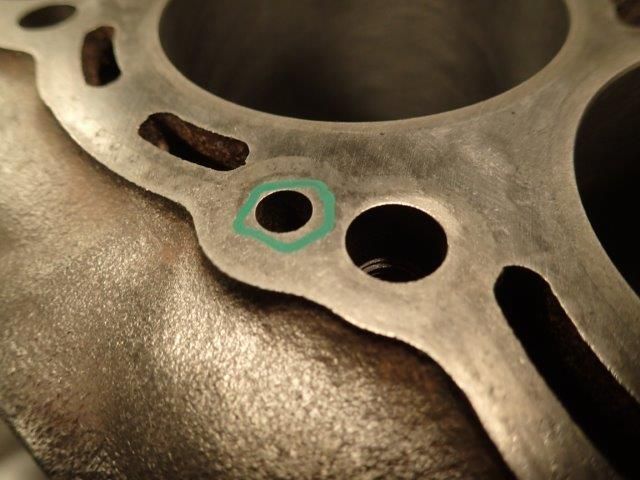
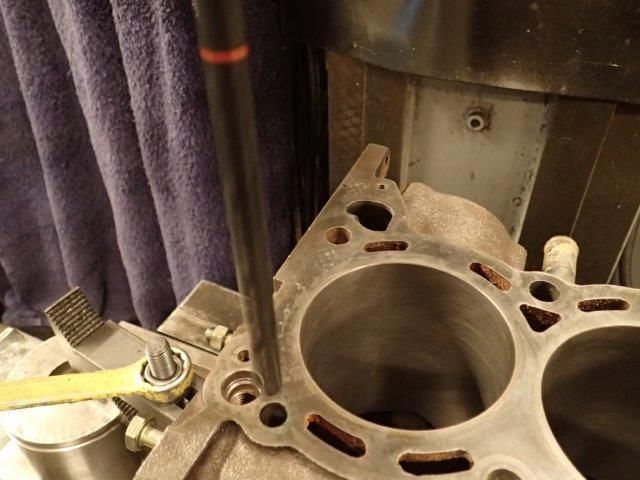
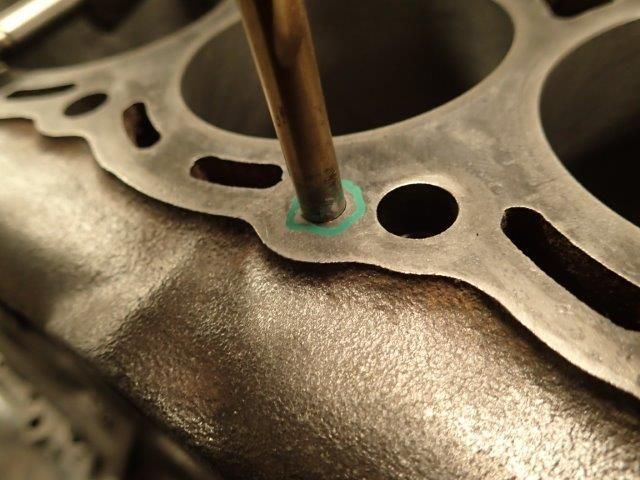
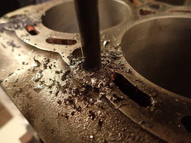
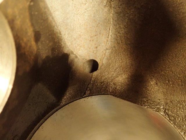
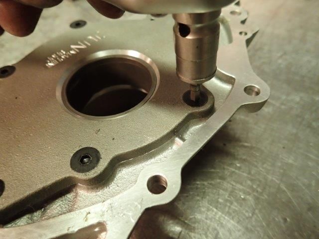
He then started drilling out the galleries
Quick look at the underside of the holes
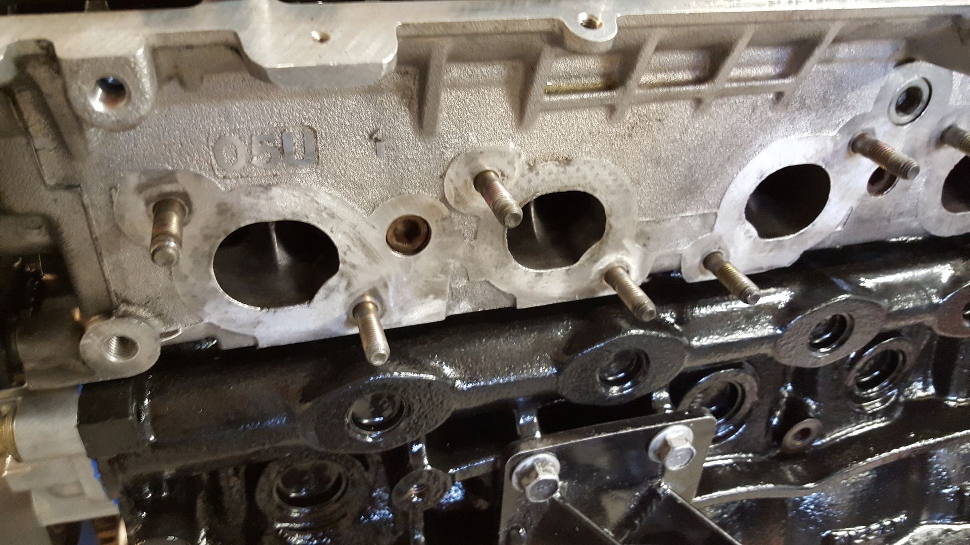
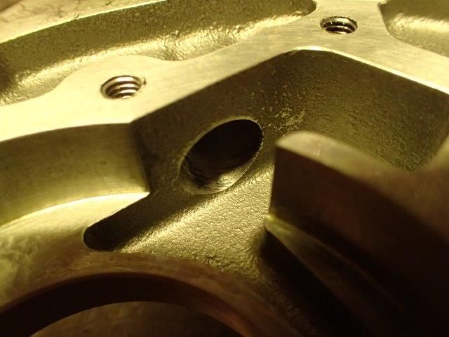
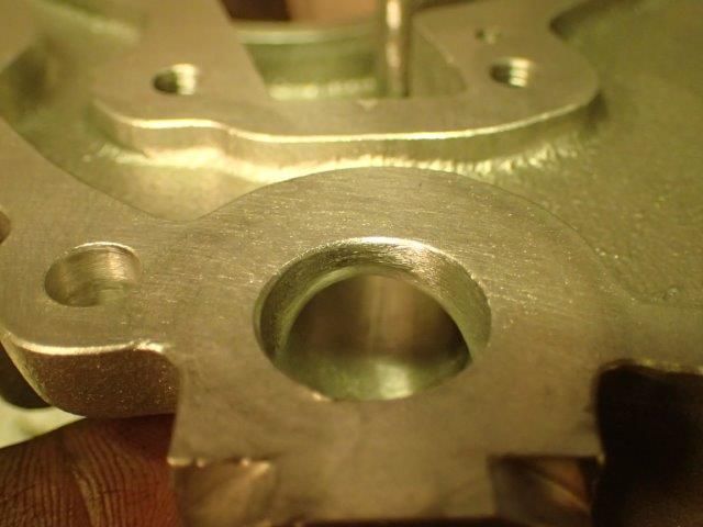
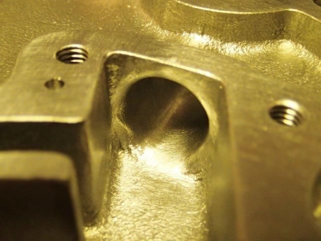
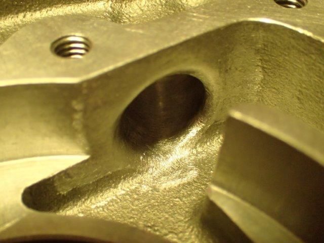
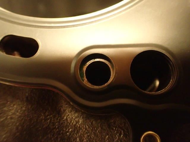
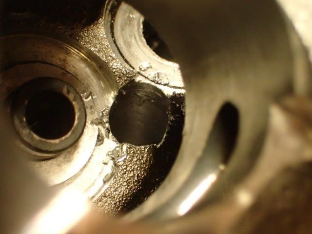
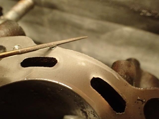
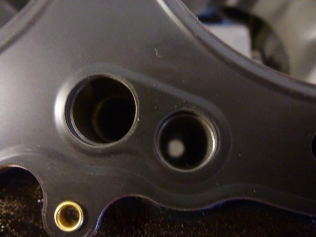
The same was done to the head
Smoothing the edges to make the oil enter easier.
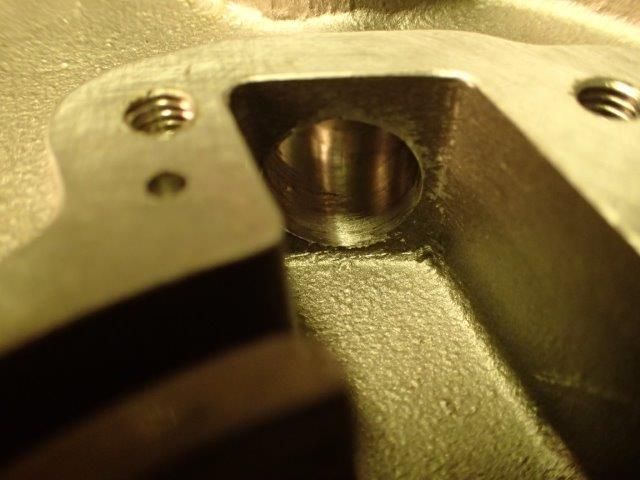
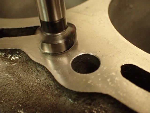
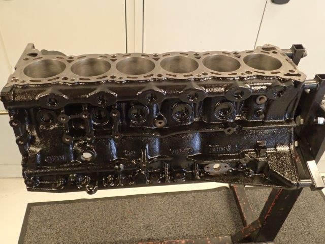
He then decked the block and mounted the 1.2mm oil restrictor.
Smoothing the edges
And the final result
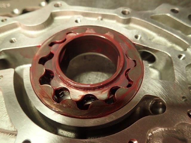
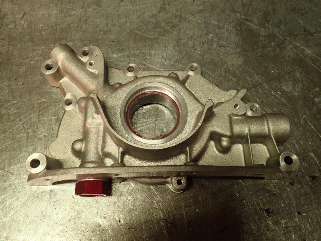
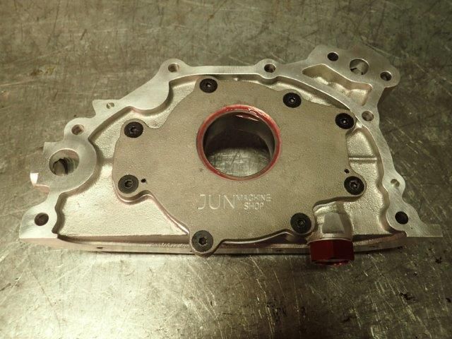
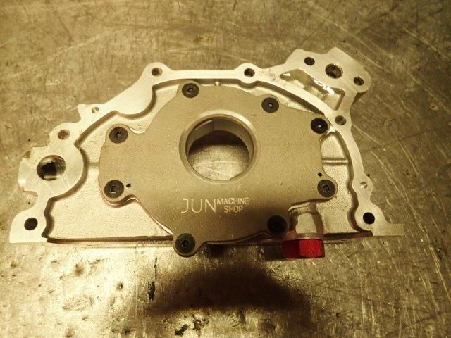
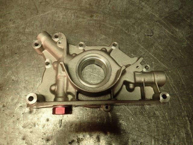
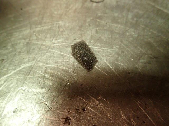
The oil pump did also get some work done. This is a JUN oil pump, which is supposed to be high quality products. This is not always the fact. Lets take a closer look.
First thing that showed up was this foam piece..... :dontknow:
-
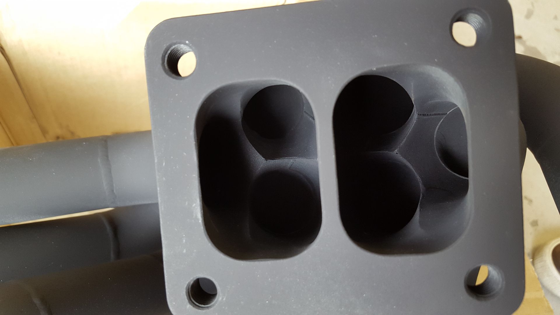
Okay. Have done a bit since last time. The 6Boost manifold did arrive at last, and this is high quality craftsmanship.
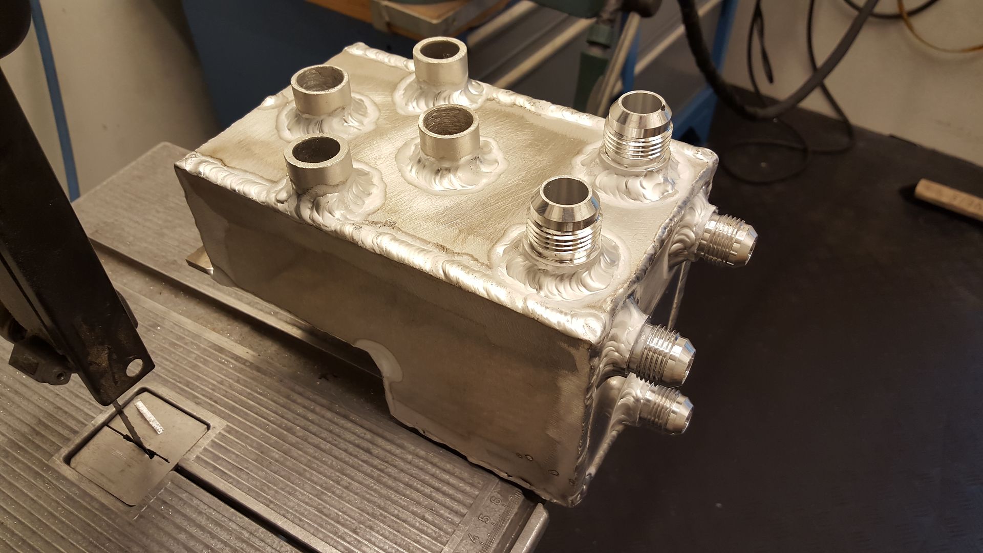
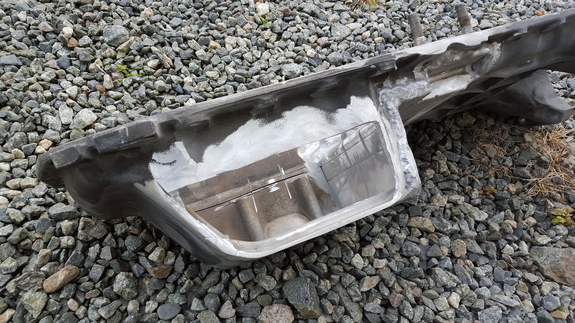
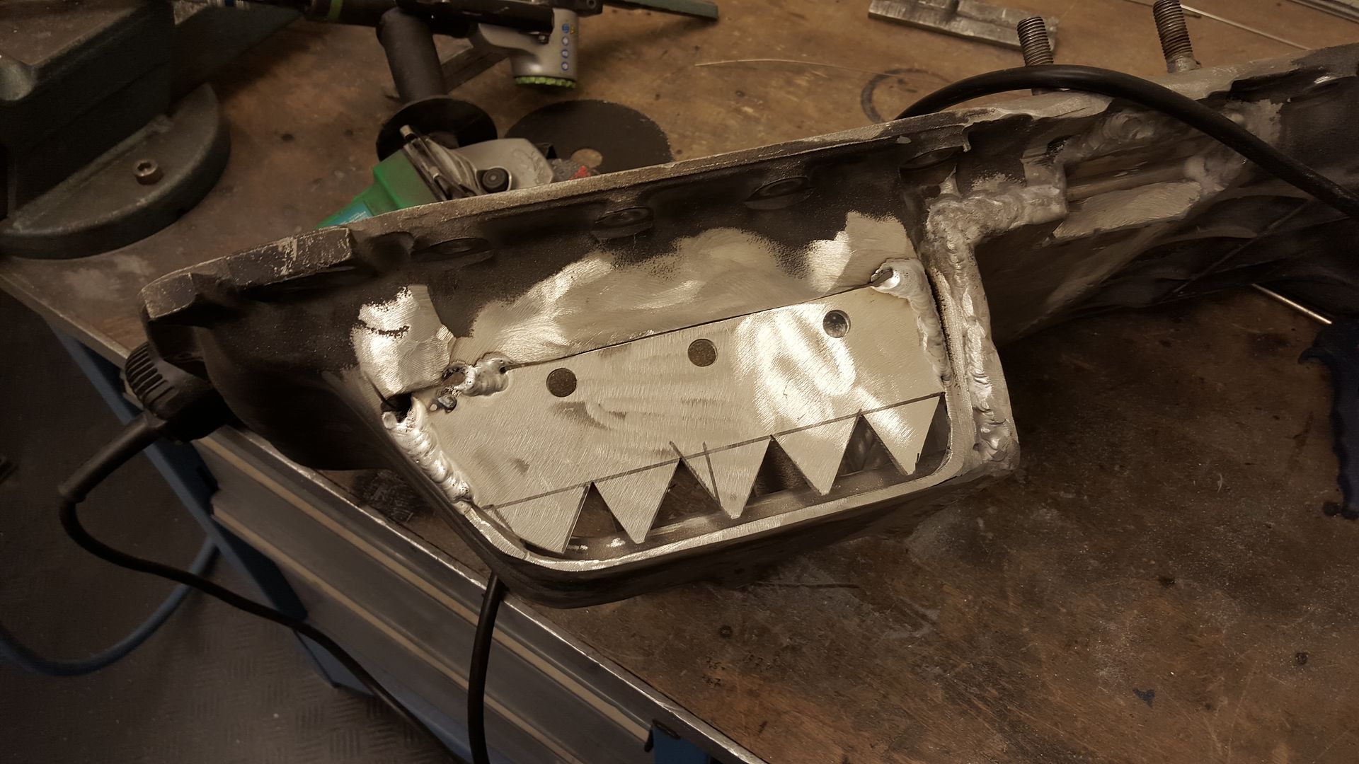
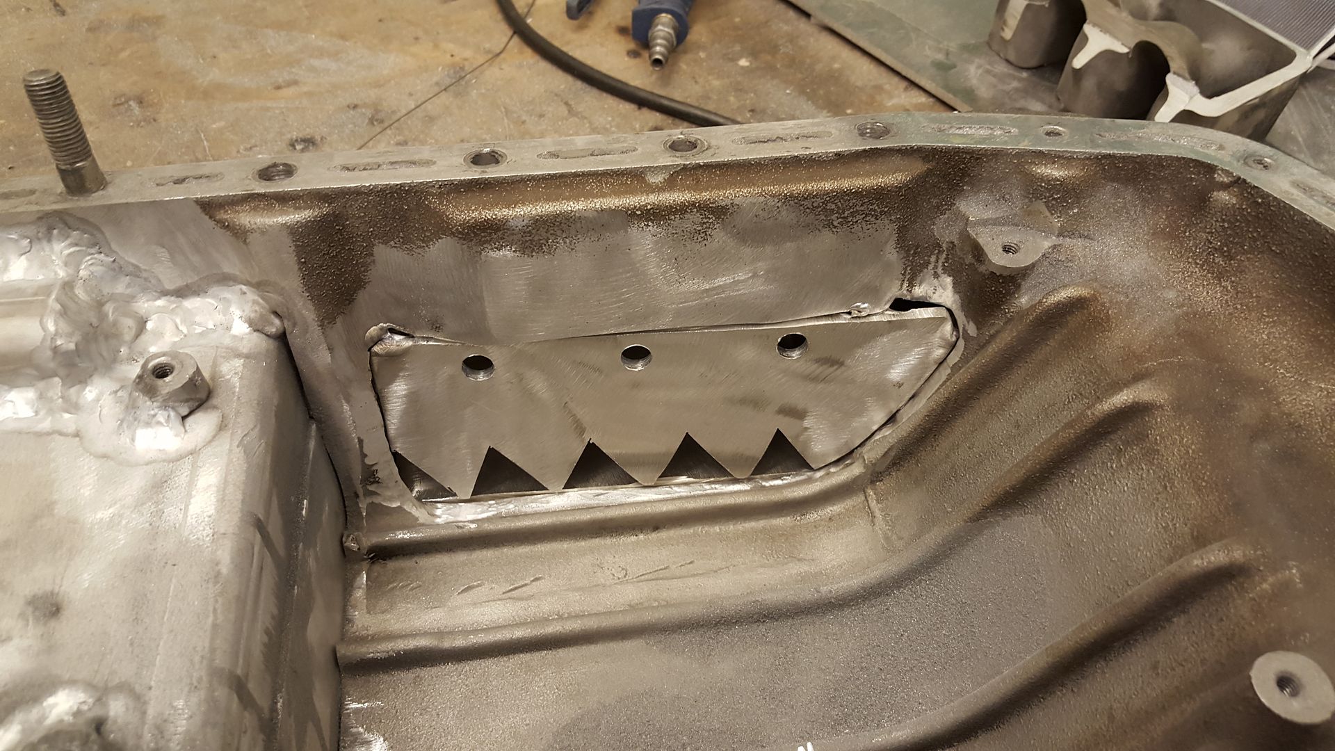
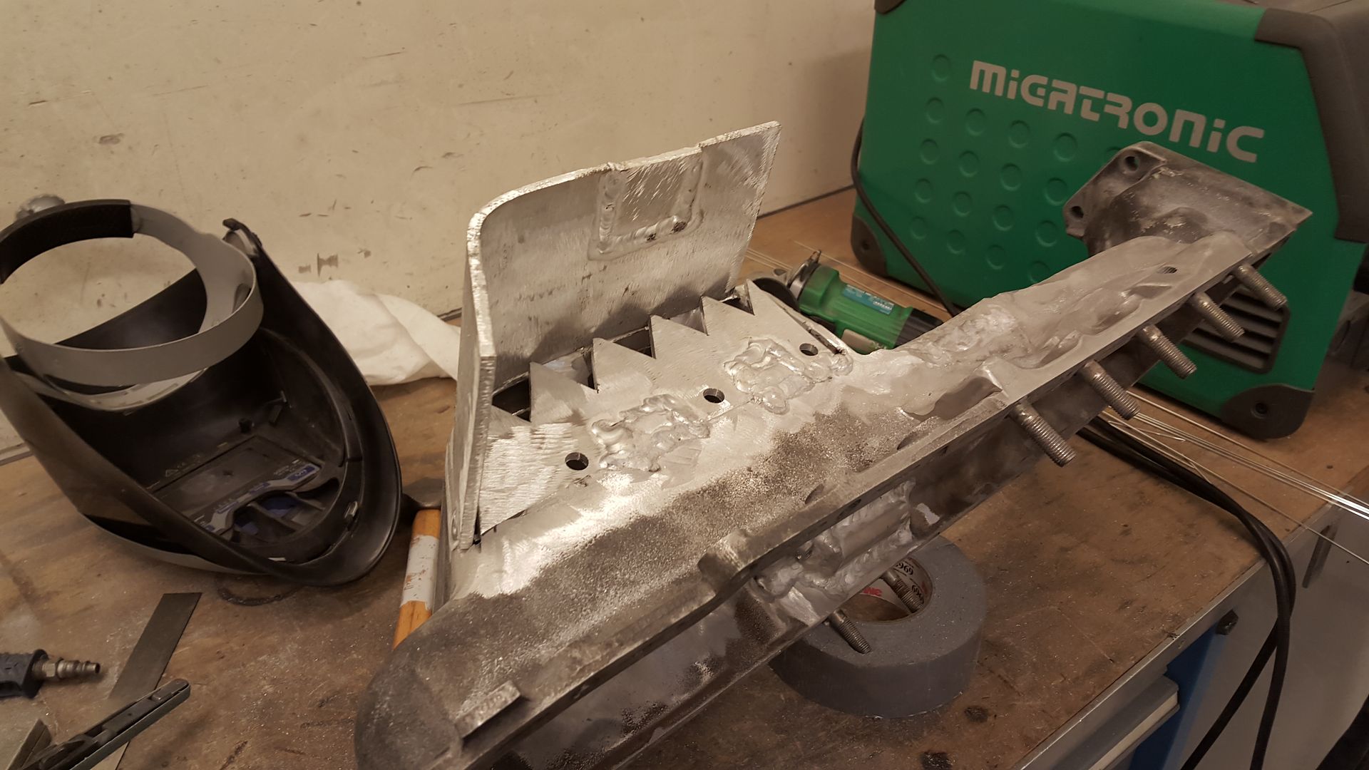
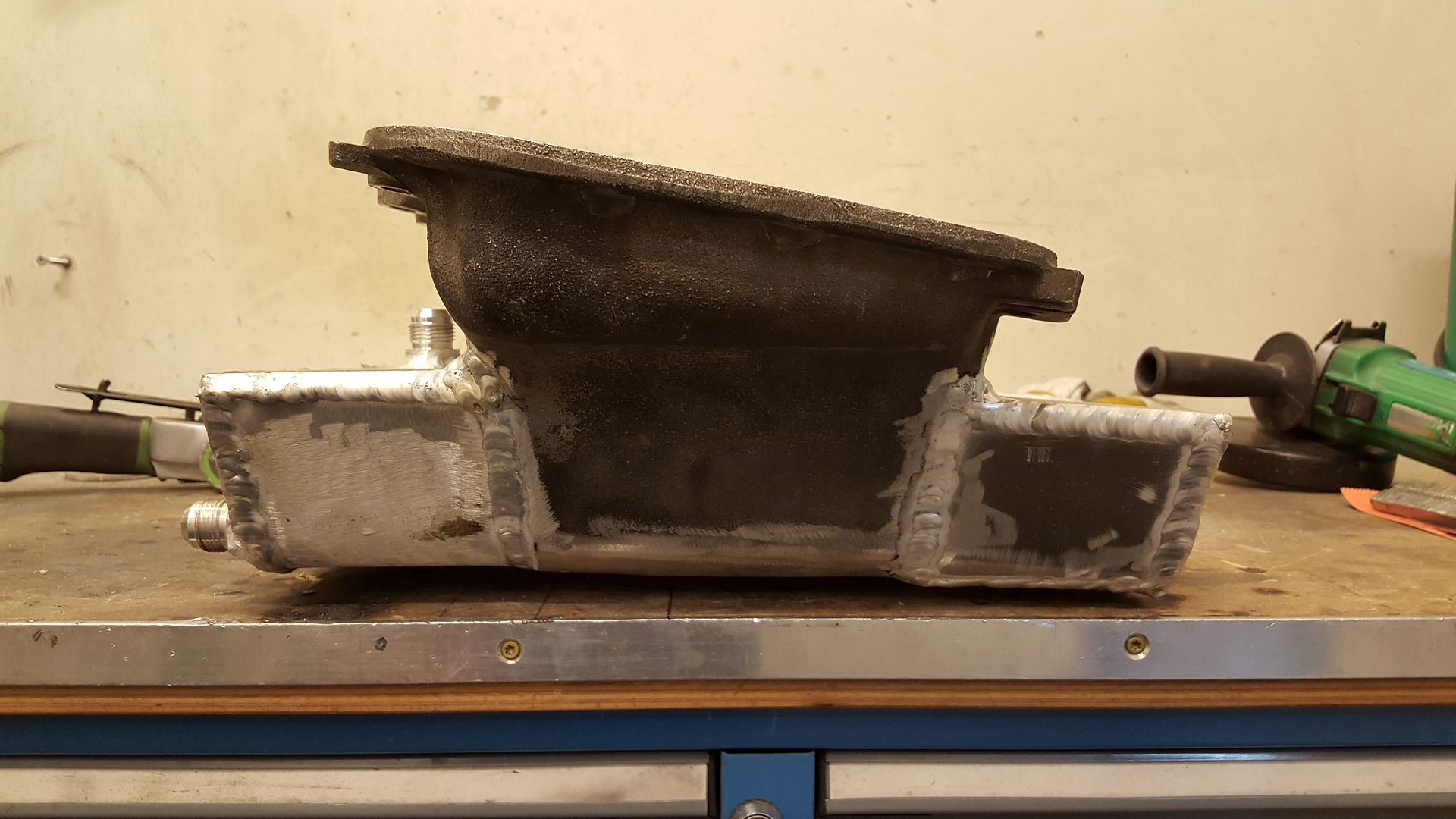
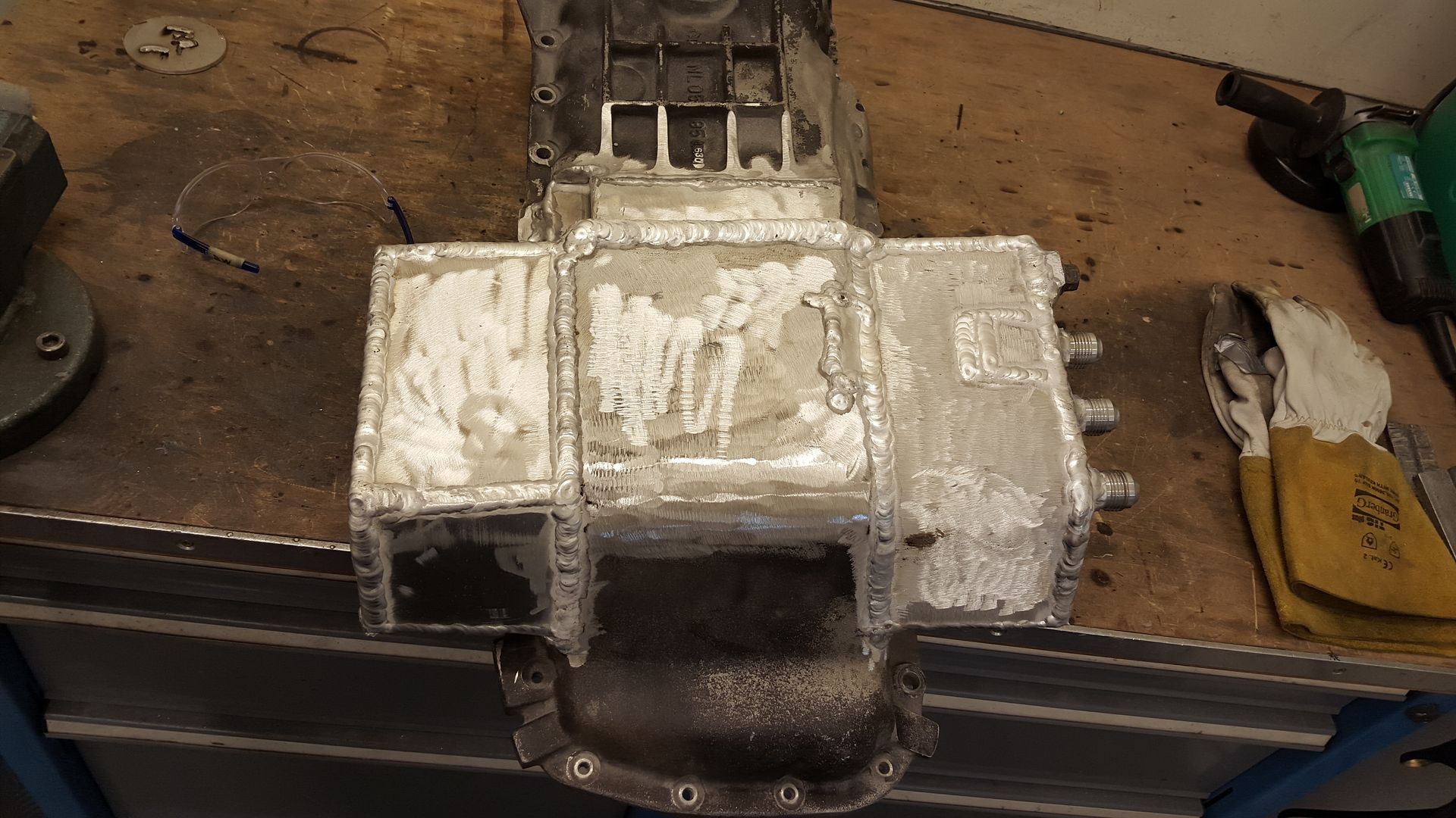
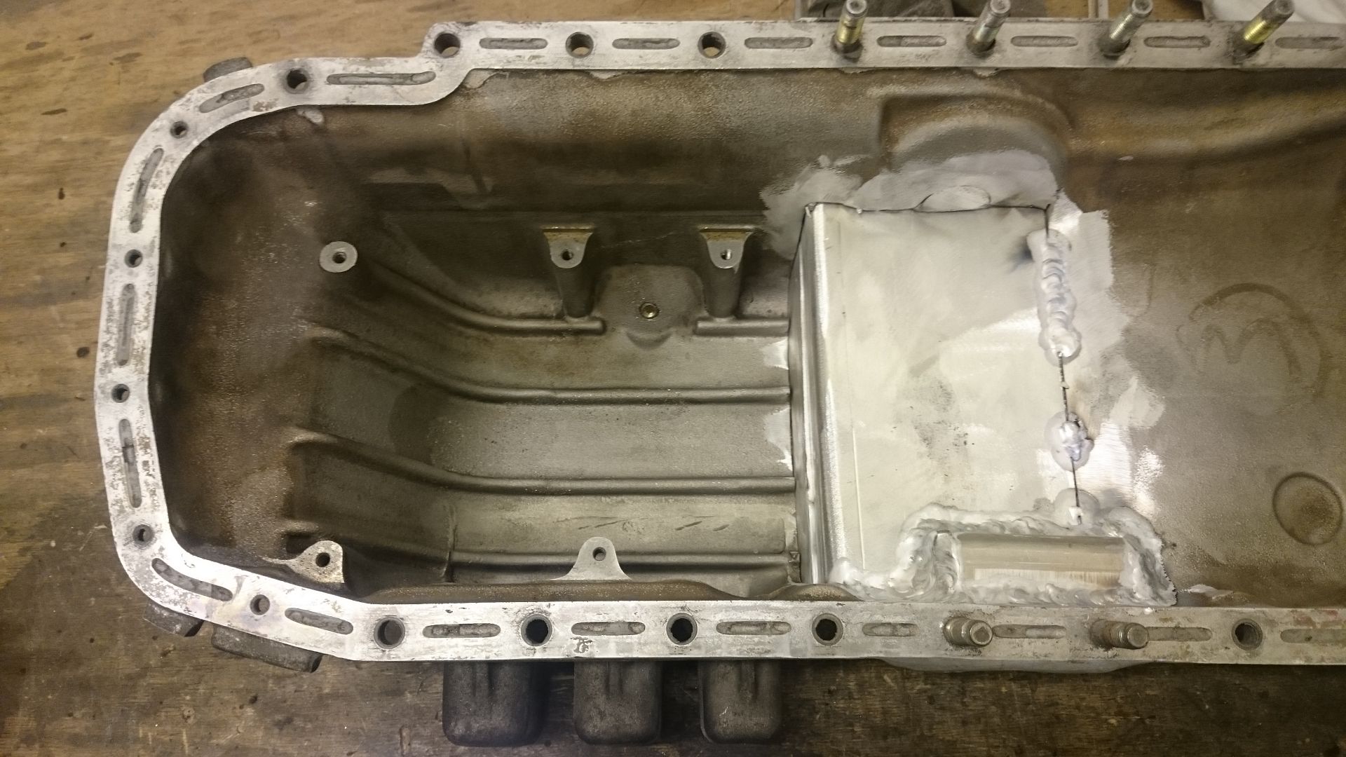
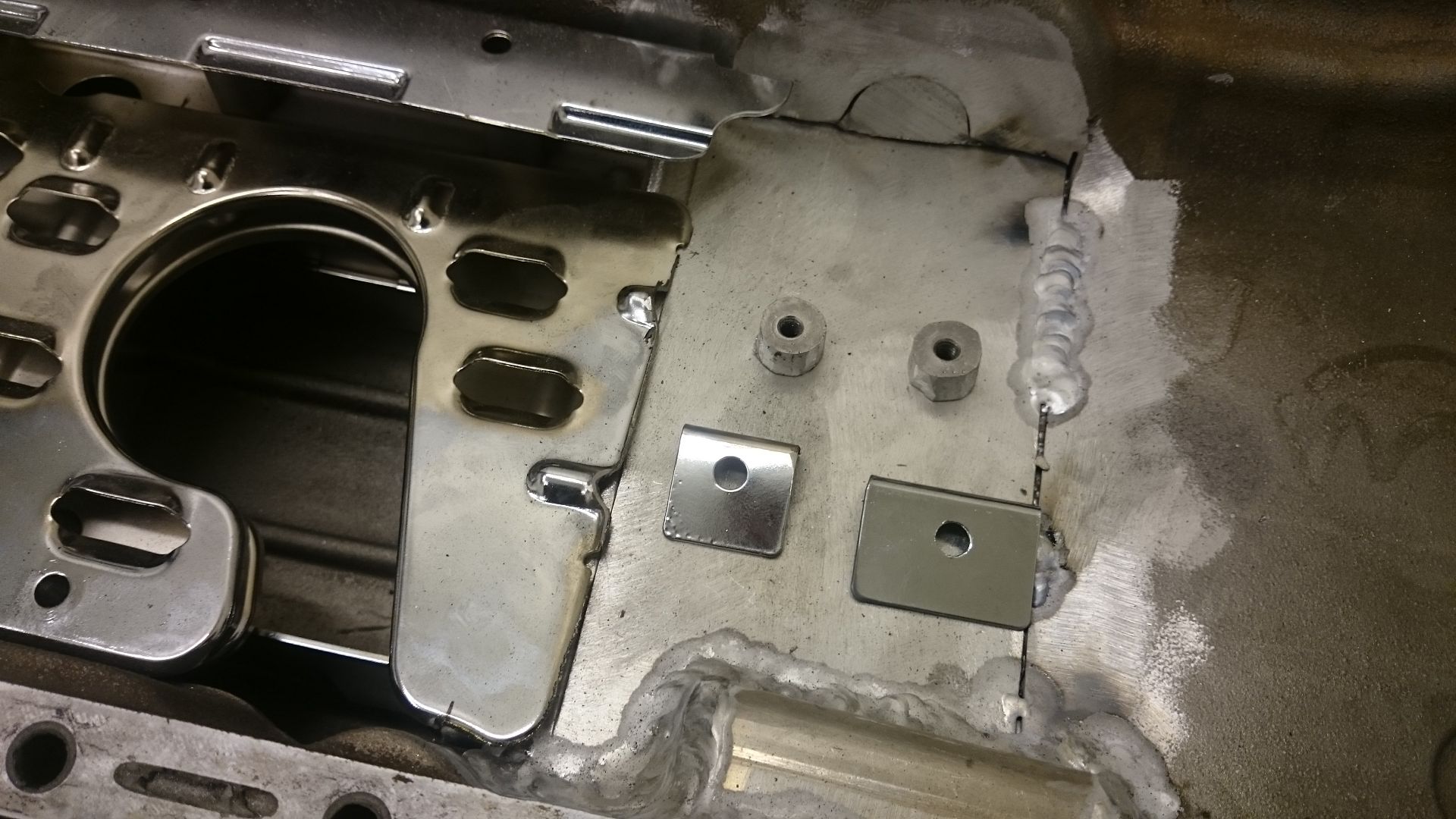
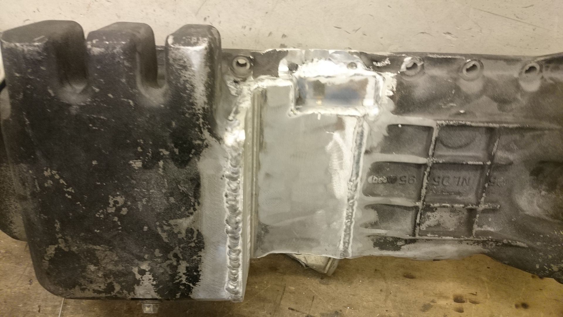
The oilpan is done. Extended the sump and made a kind of baffle inside. I have not welded aluminium before working on this oilpan. But I'm getting to it after all these hours on this oilpan.
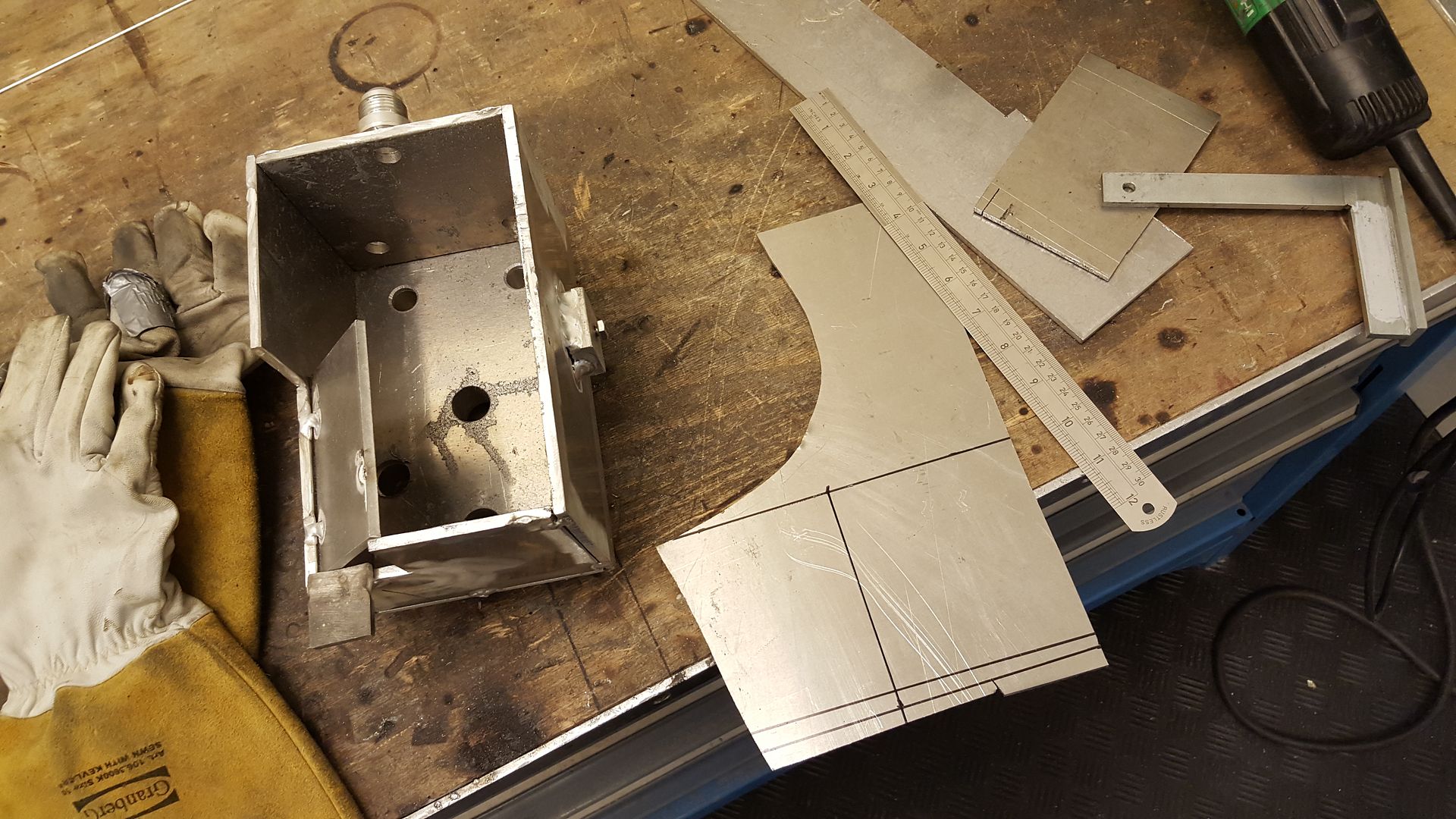
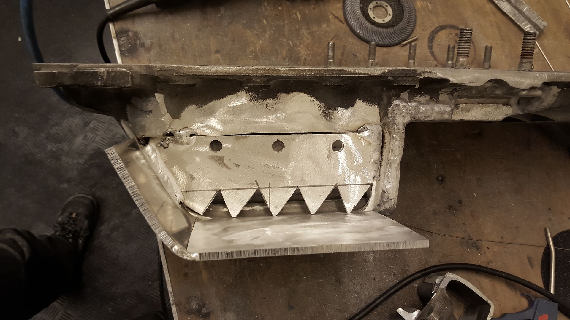
First I started cutting off the sides and made the baffle plates.
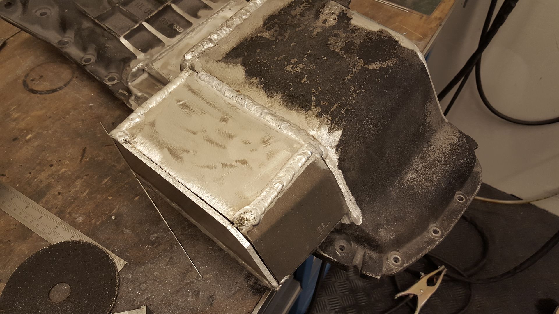
Then it was to box it in.
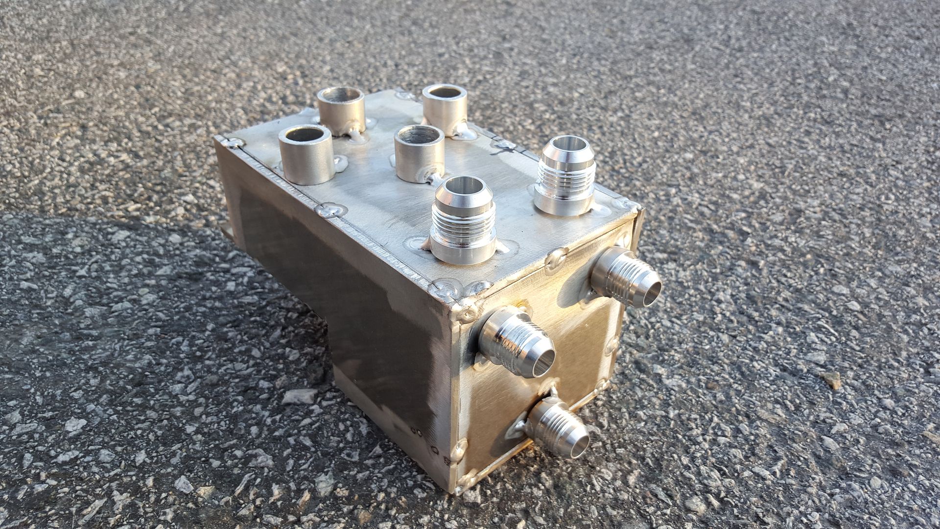
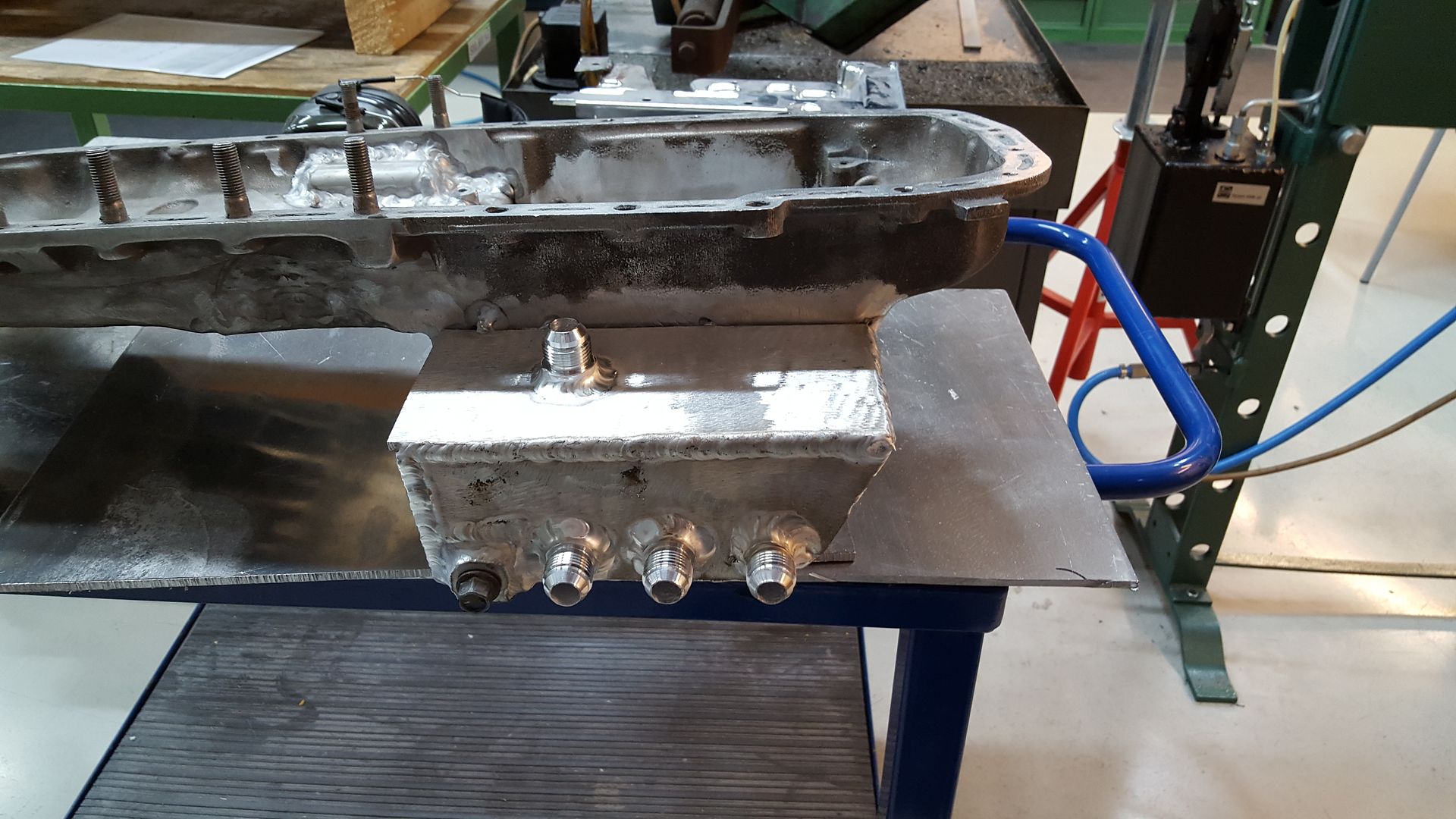
Went on with 4pcs AN10. There is some spare, but I want to have some extra in case there will be different catch can solutions in the future.
And the final result after hours of building
I have also buildt the pressure pipe for the intake side.
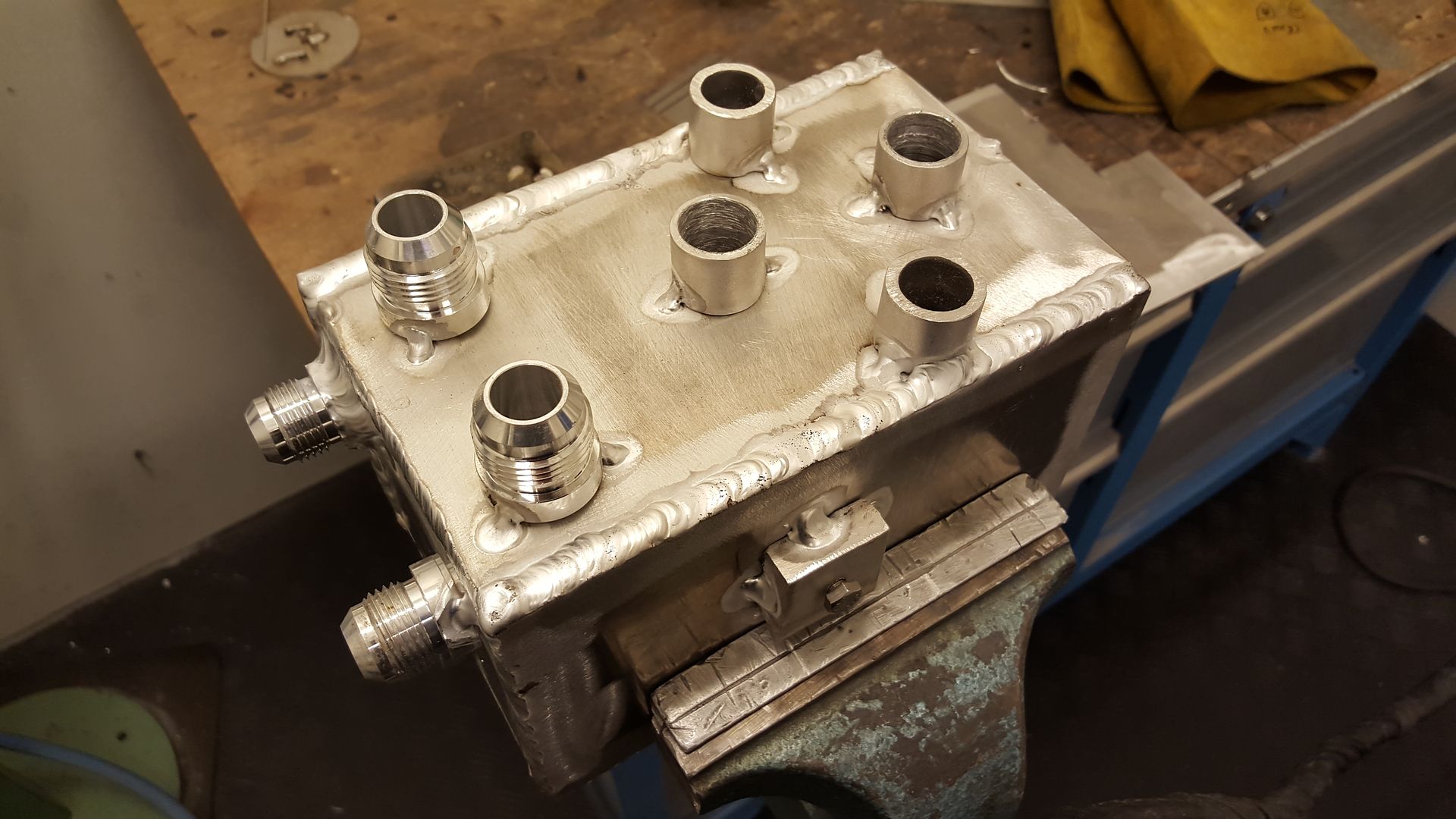
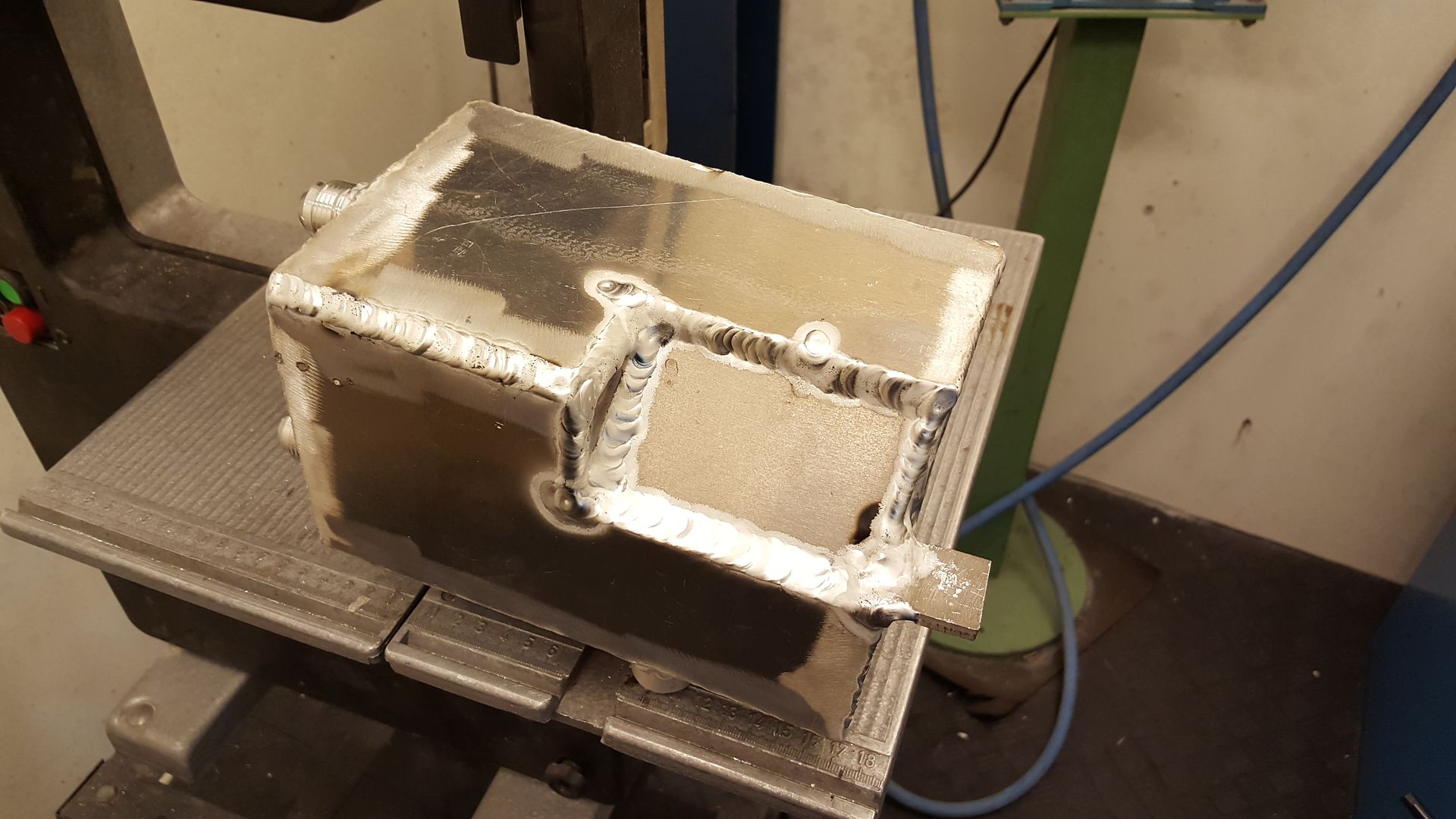
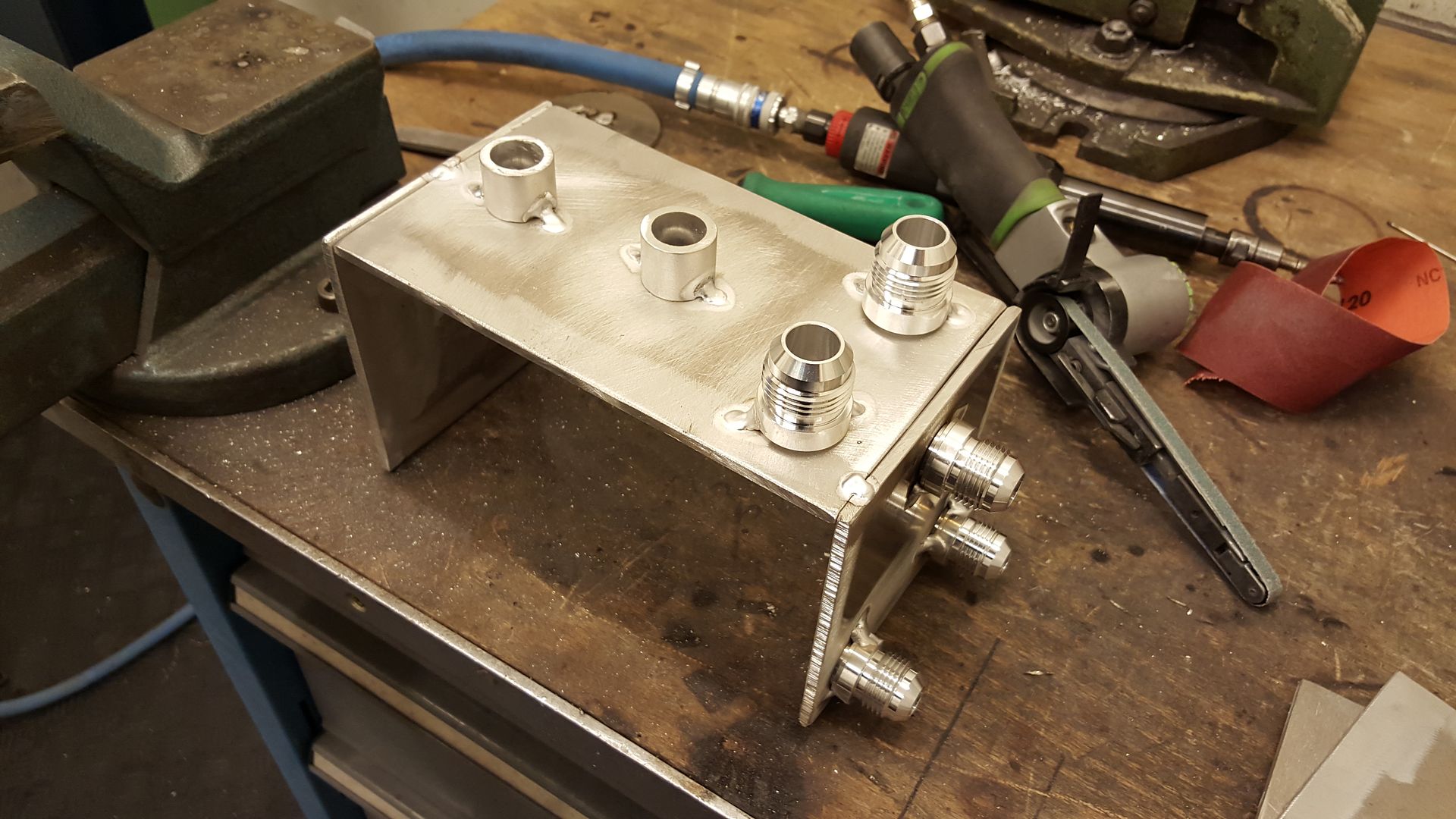
Then I buildt my catch can. This is just fixed together and tested to fit the car. It needs to be some baffles and filters inside. But the design is done.
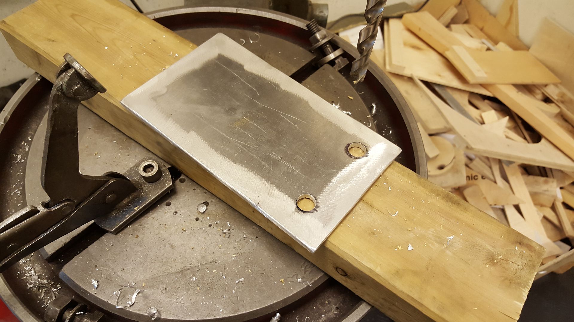
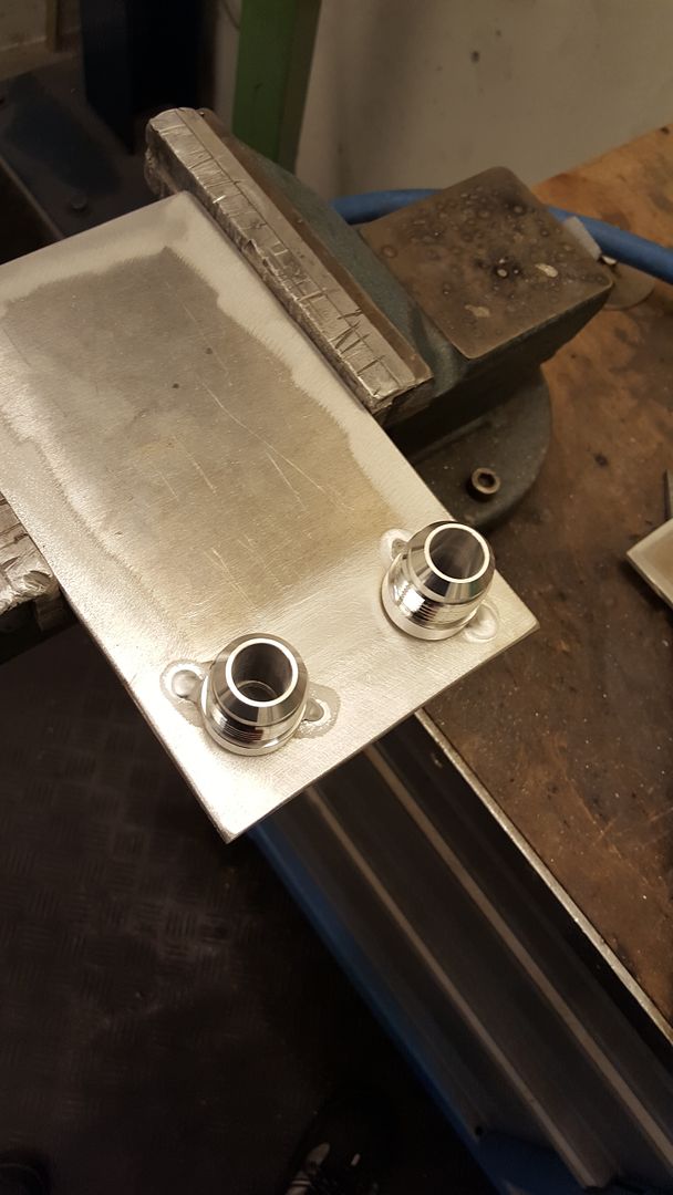
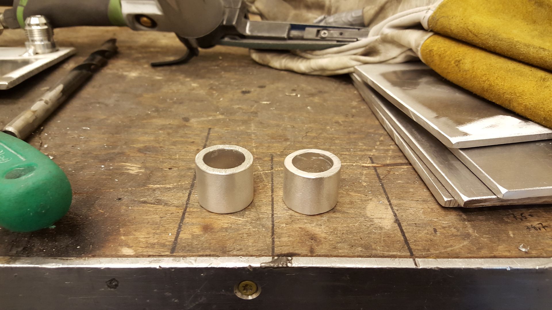
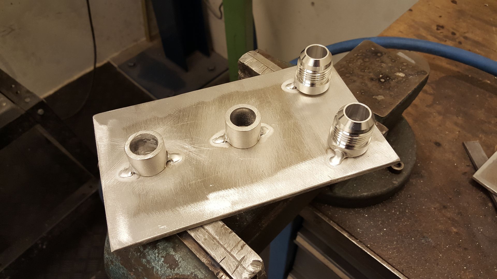
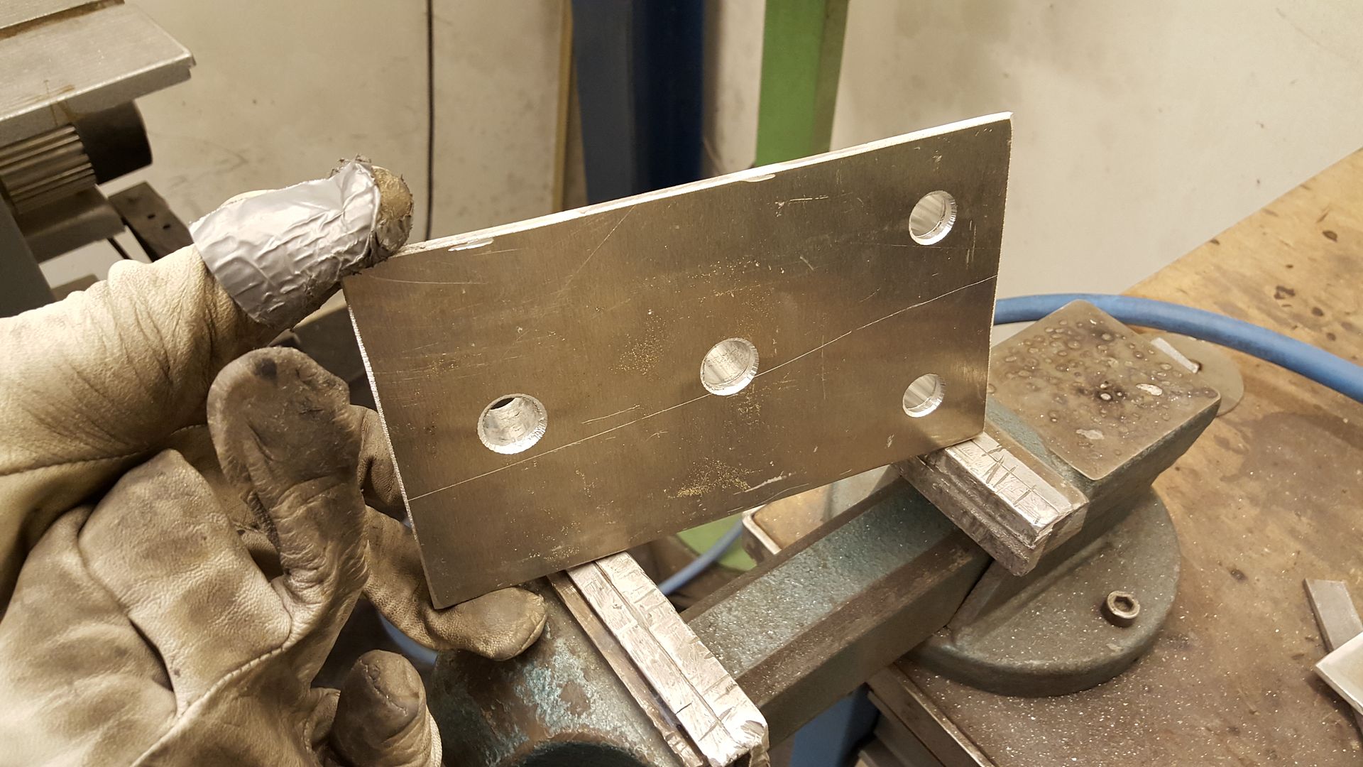
Started off with basic aluminium plates. Drilled the holes for the weld bungs
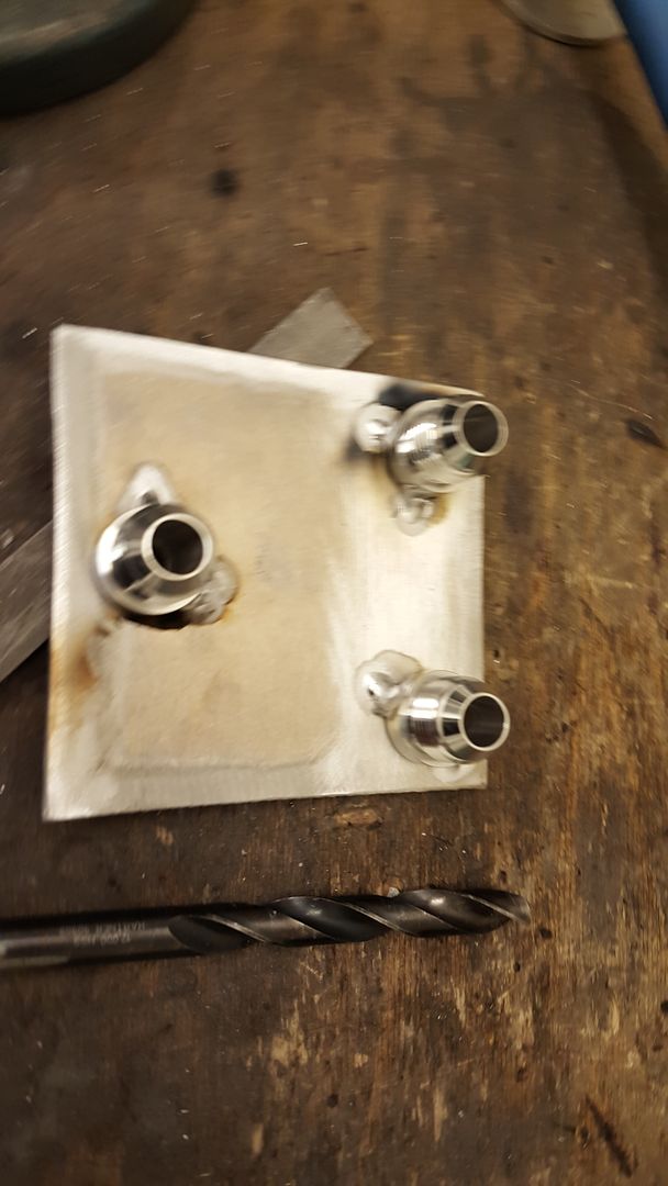
Spot welded
For the breather filters I went with regular 25mm aluminium tubing
Drilled holes and spot welded
Then it was time to spot weld it together. Getting everything in 90 degree angle is important. So I took my time with this.
-
Have done a bit the last week, not much though. In the middle of buying a new appartment and stuff like that. So, have to make that the priority.
The engine is delivered to the engine builder, and just waiting for him to do his magic. Other than that there have arrived some parts.
Nismo thermostat:
AN12 rocker cover breathers:
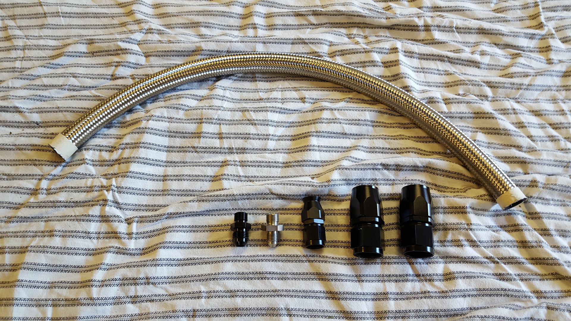
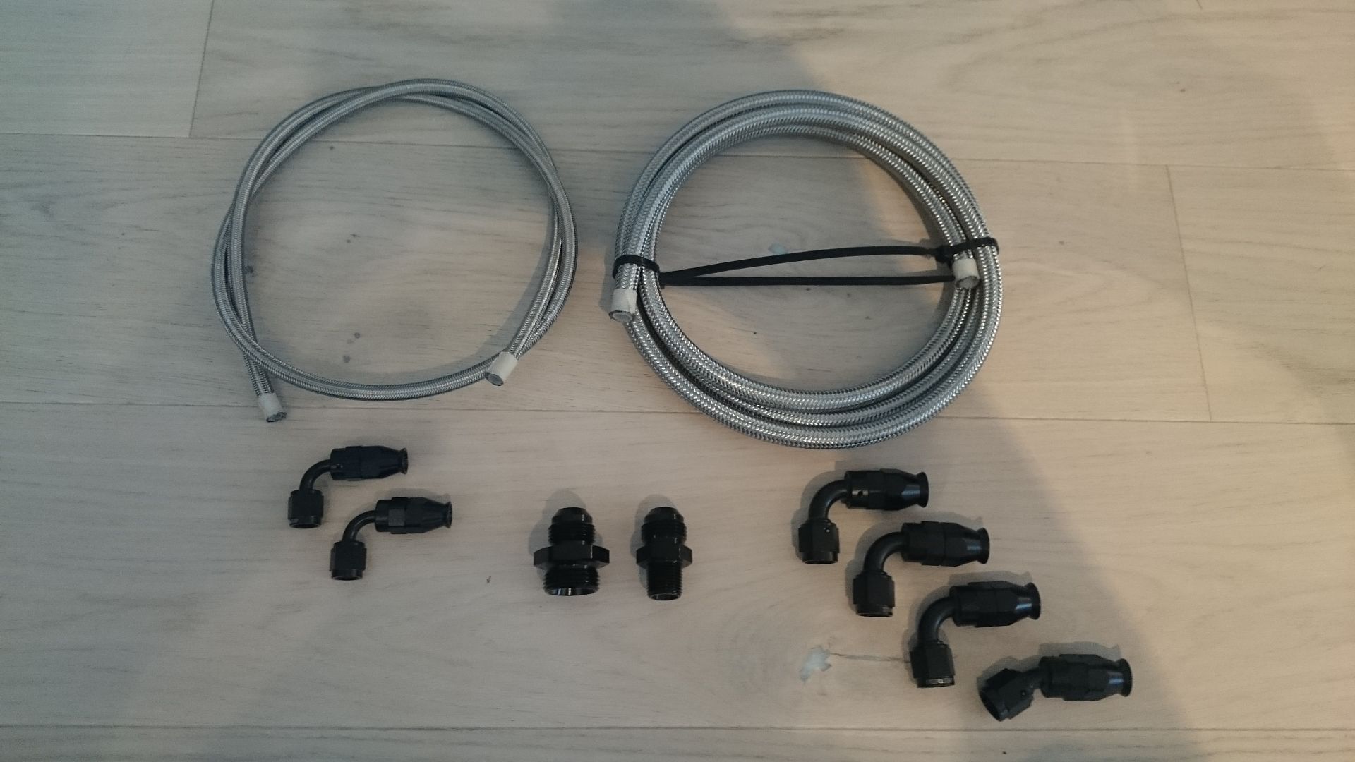
Oil line and water line with fittings for the turbo
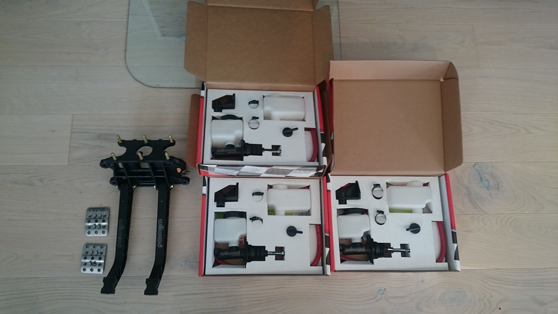
The Wilwood pedals and masters
Custom driveshaft
-
-
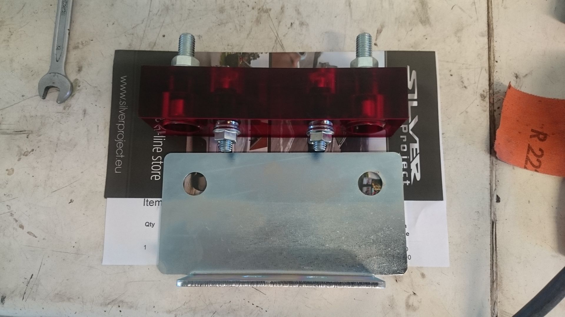
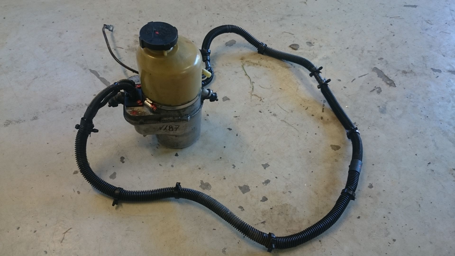
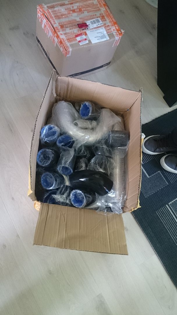
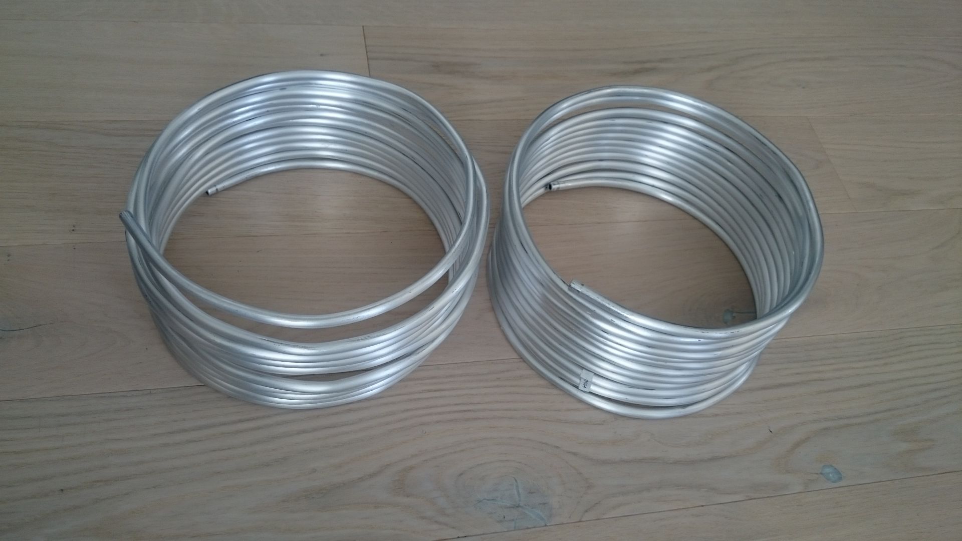
Got some more things done today, and I got four packages in the mail
What turned up today was Silver Project gearbox mount, used Opel Zafira electrical powersteering pump, AN-8 (9.5mm) aluminium tube rolls and a lot of aluminium tubes and silicone hoses for the intercooler.I know I'm not good at posting pictures of things while it is in progress, and that is simply because I'm working with full focus and dedication. So it does not come to my mind before the product is done.
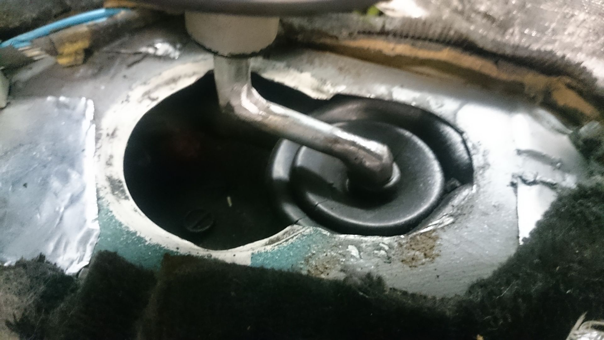
So. The other RB25/26 E30 build I have seen have had the shifter come up in the center of the stock shifter hole. If the engine had been in that position, which is about 2 3⁄4" more forward, the car would gain even more load on the front axle. So for me it was not an option. That lead to some cutting and some modding of the shifter itself.
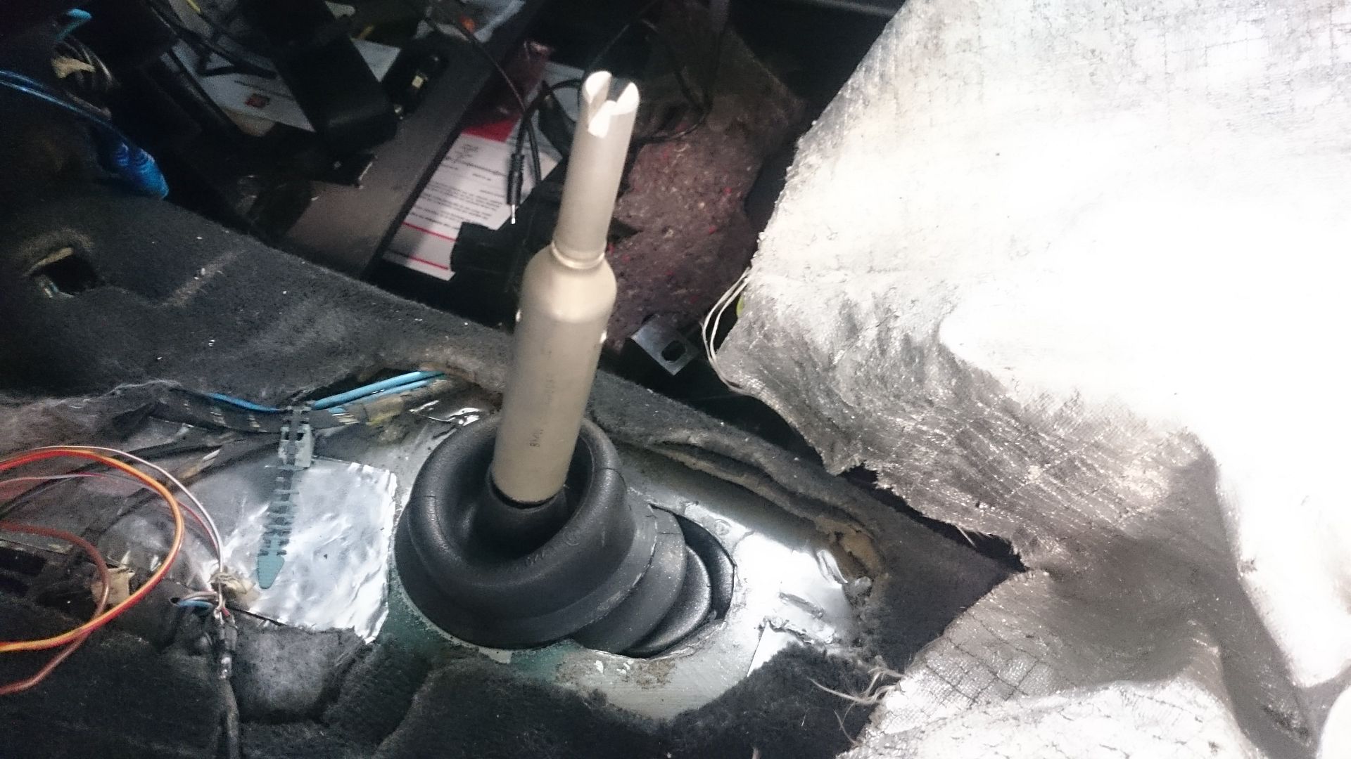
I simply cut out to make room for the mechanism, and then I build my own shifter. Parts that is used is the Nissan lower part, a regular bolt and the top of a E39M5 shifter. Meaning I can camoflage the whole Nissan shifter. So I can still use my Sport Evolution gear knob, and the ///M stitched suede boot. Will need to get a custom shift pattern top for the knob, since it have reverse on down right.
The shifter also feels a bit sloppy, so I might get a Ebay short shifter kit and remodel it a bit.
Here is how it turned out:
The new gearbox mount:
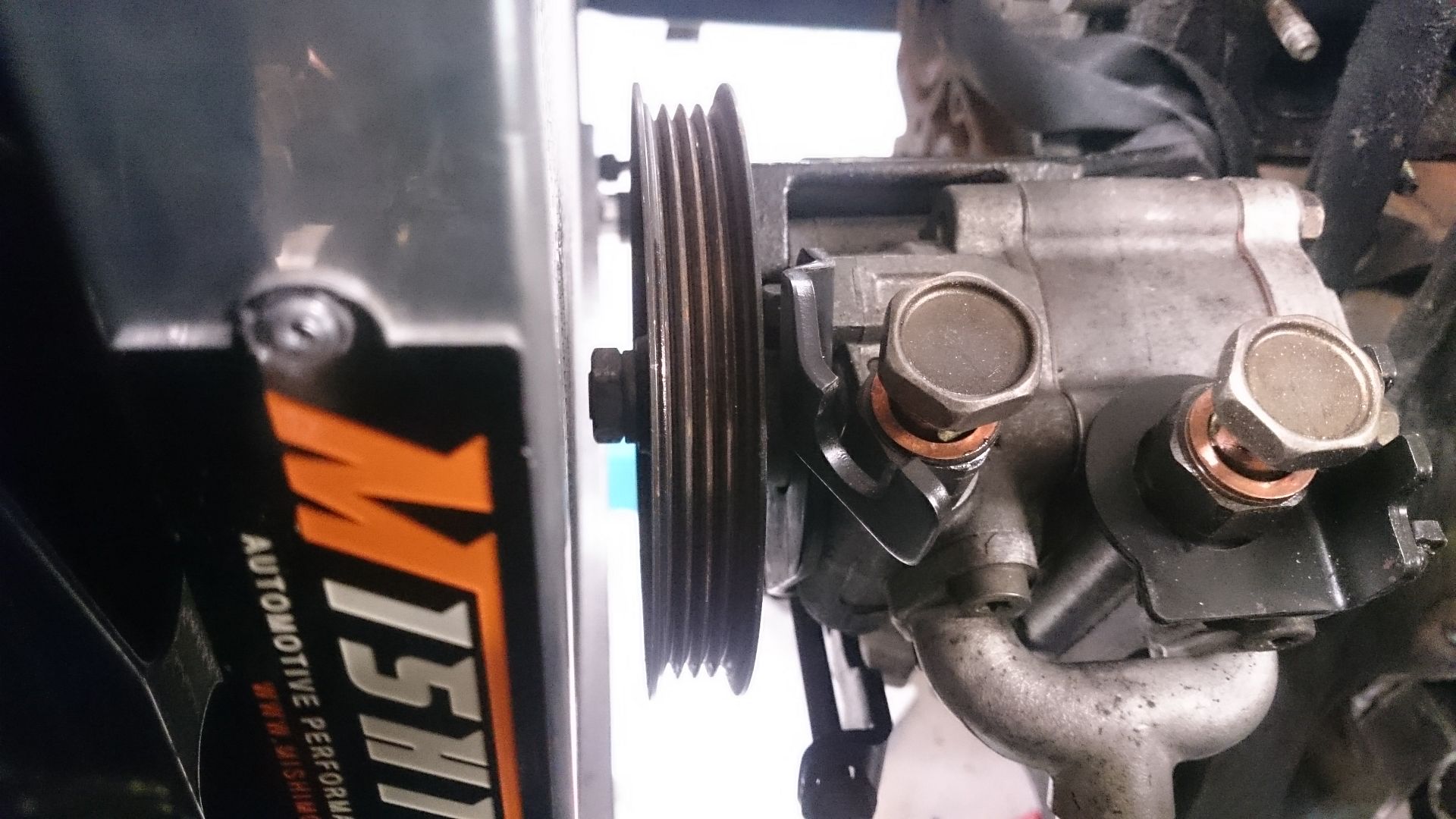
Opel Zafira powersteering pump:
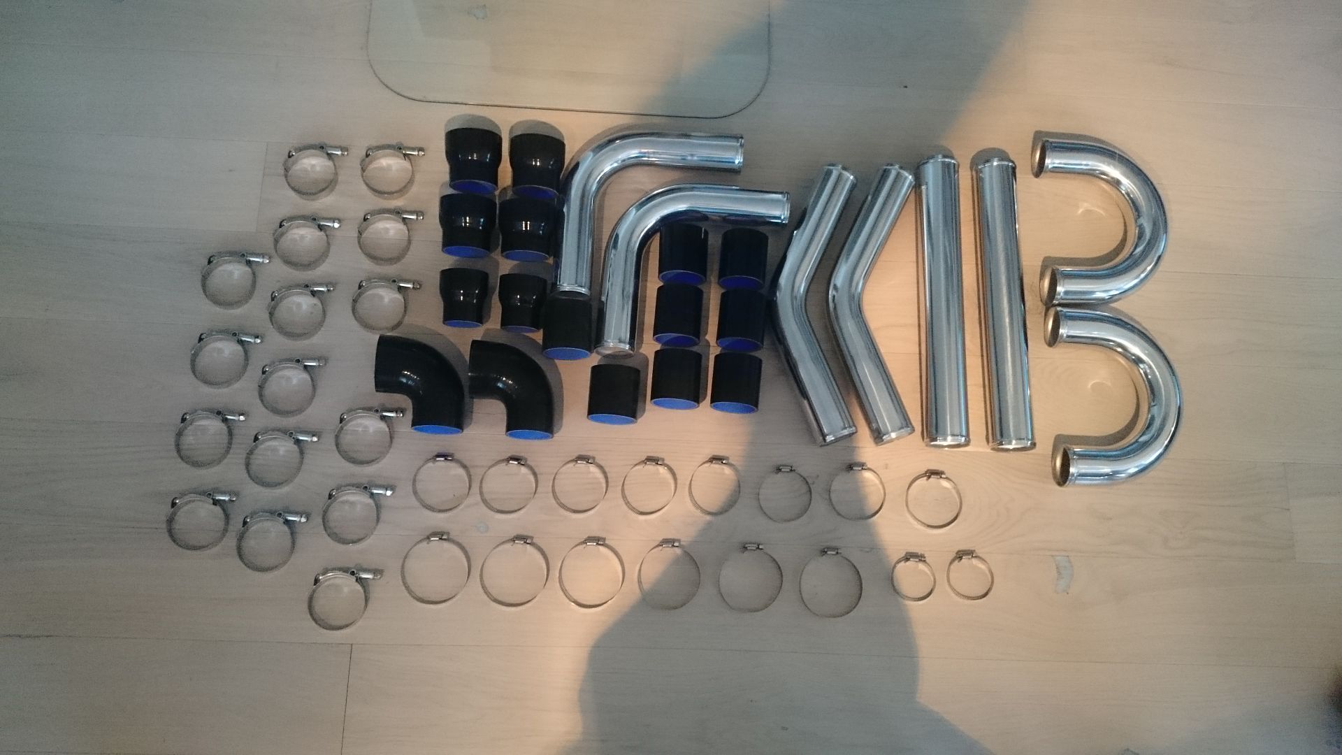
A box of pipes and hoses. Will lay out on floor and take picture later, was not time for that today.
Just stared to play a bit with the tubes, to have a quick look. They will be painted matte black after welding.
Looks like it will fit. Cant wait to start on the downpipe....nightmare.
Quick overview
And the two rolls of aluminium tubing for the fuel feed and return lines.
-
Well well. Some more parts have arrived. I love Ebay <3
I have been back and forth about how I'm going to build my engine mounts. My first idea was to use the GTR rubber, but placing them in the crossmember did not work. They have a steel plate surrounding the rubber, and them being wide it was hitting the chassis. From my experience that will result in a lot of noise.
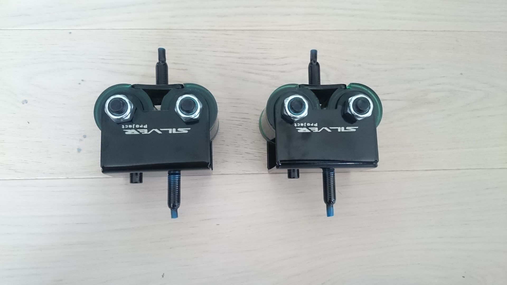
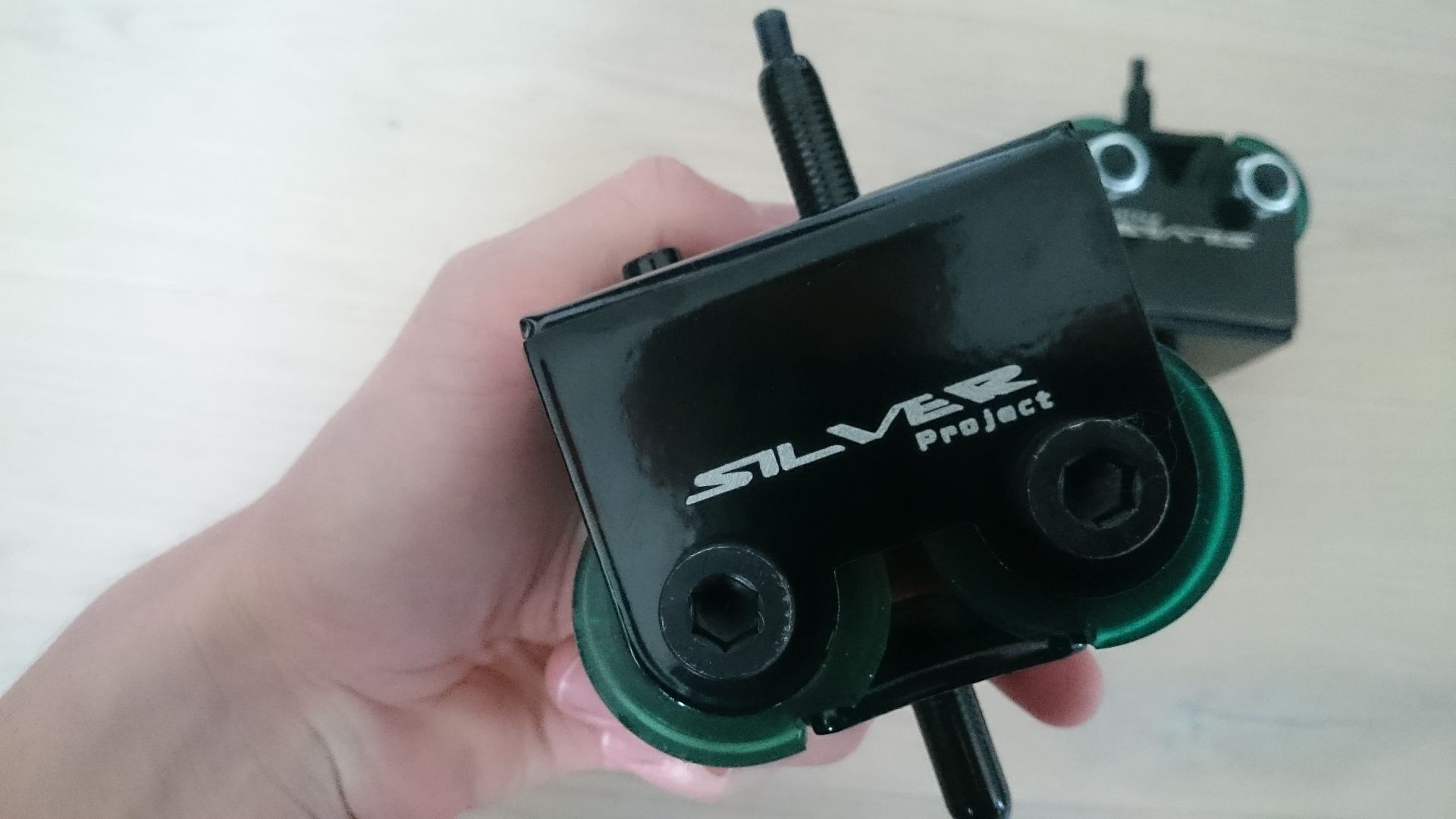
After thinking and searching the internet I found a shop in Poland named Silver Project that had these solid looking (and fair priced) polyurethane mounts.
Since I have modded my crossmember to fit E36M3 mounts, I went for them for this build as well.
In 2014 I had Vibra Technics competition mounts for E36M3, and when I pulled them out the bolt was bend and the rubber had given up. And that was after ONE track day. They cost a lot of money as well, so they was not an option.
The Silver Project mounts is made of steel and have two round polyurethane bushings. They are stiff as hell, and I just hope there will be not to much noise in the coupe. But after all, they are E36M3, so I can swap them for what ever E36M3 mounts I want.
Gearbox mount is also bought from the same shop. That one is for the R33 GTS gearbox, and have not arrived yet.
So I have build my own mounts and (finally) placed the engine in the car. I have started to work on the new shifter as well, but I have no photos of that.
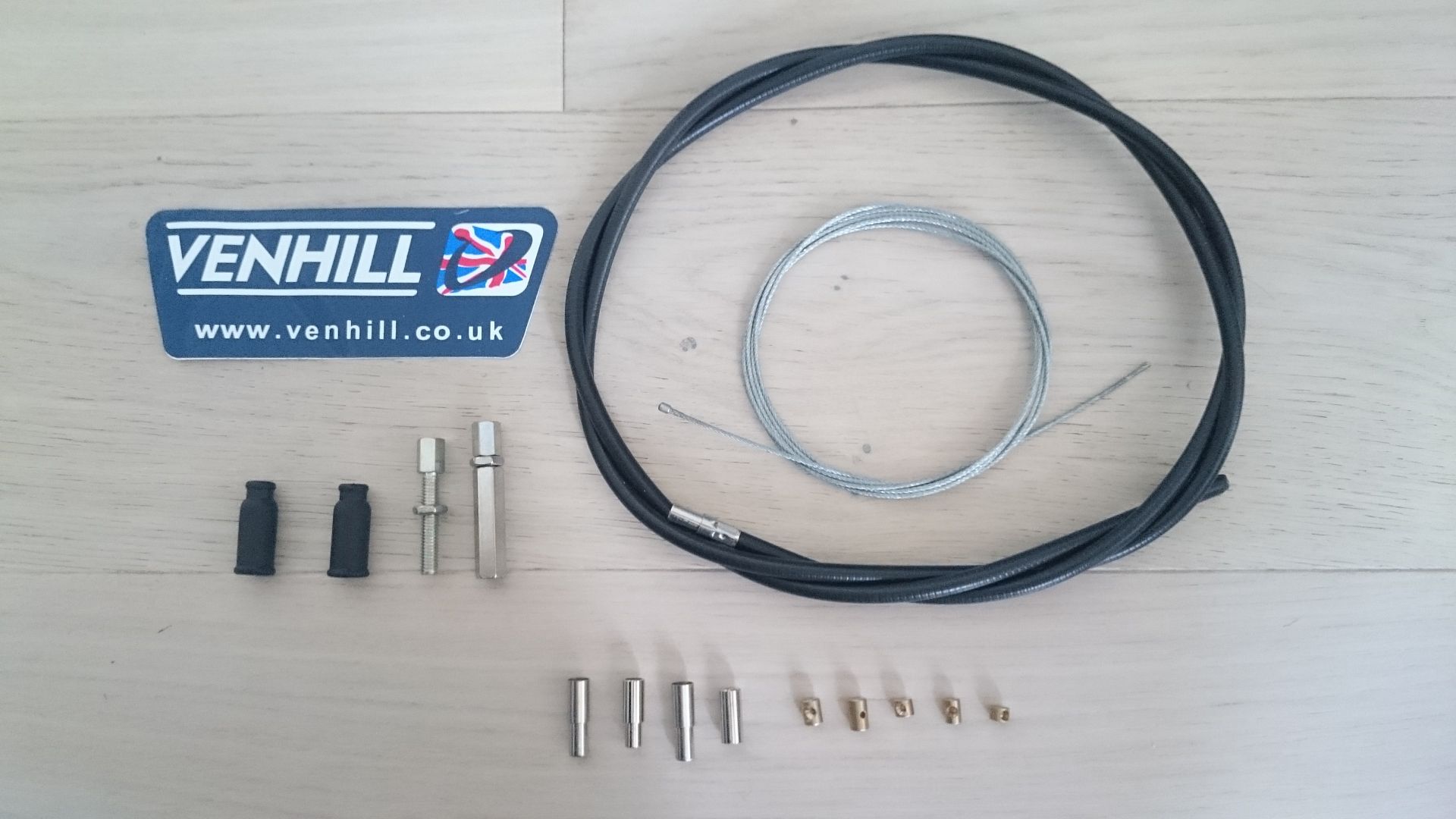
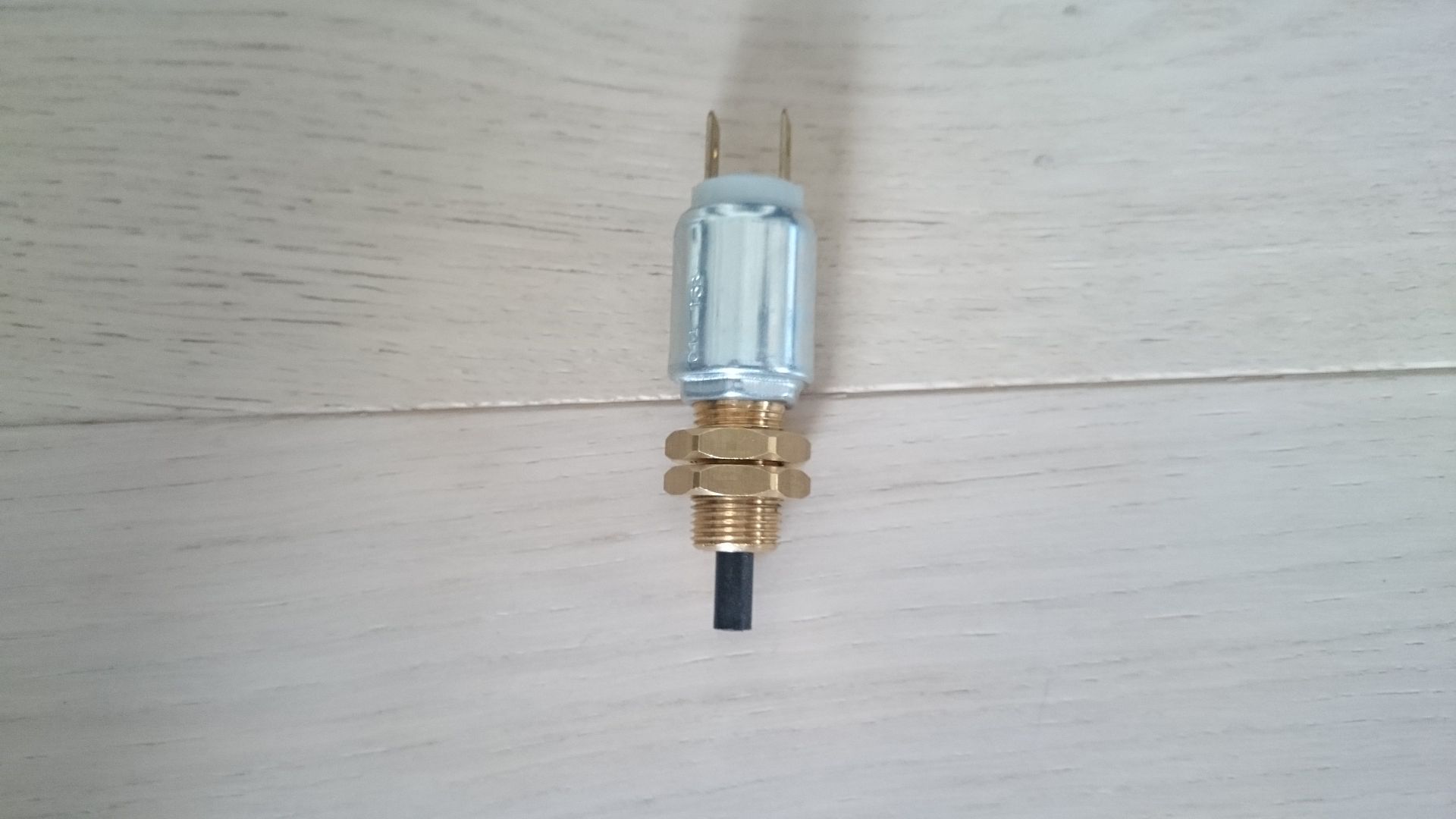
A universal throttle cable have arrived, as well as a brake light switch for the Garagistic pedal box bracket. Mine was square, and that one needed a round.
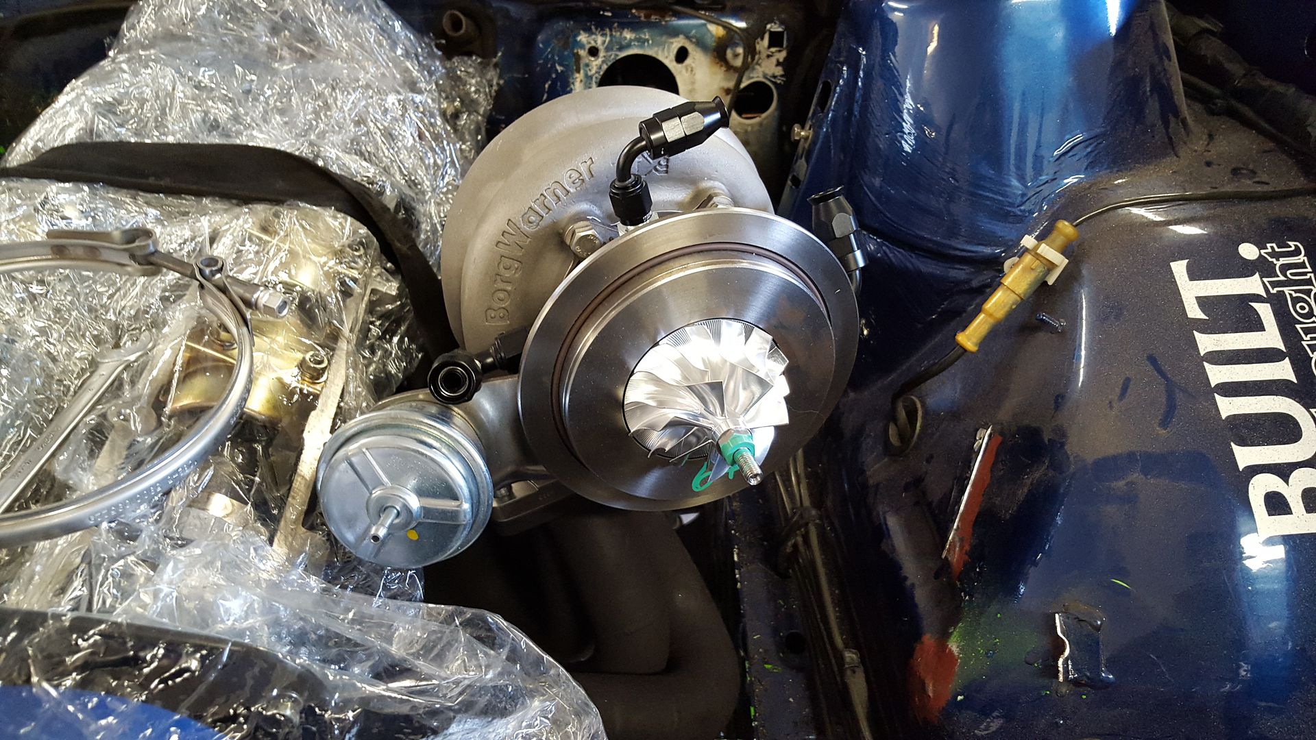
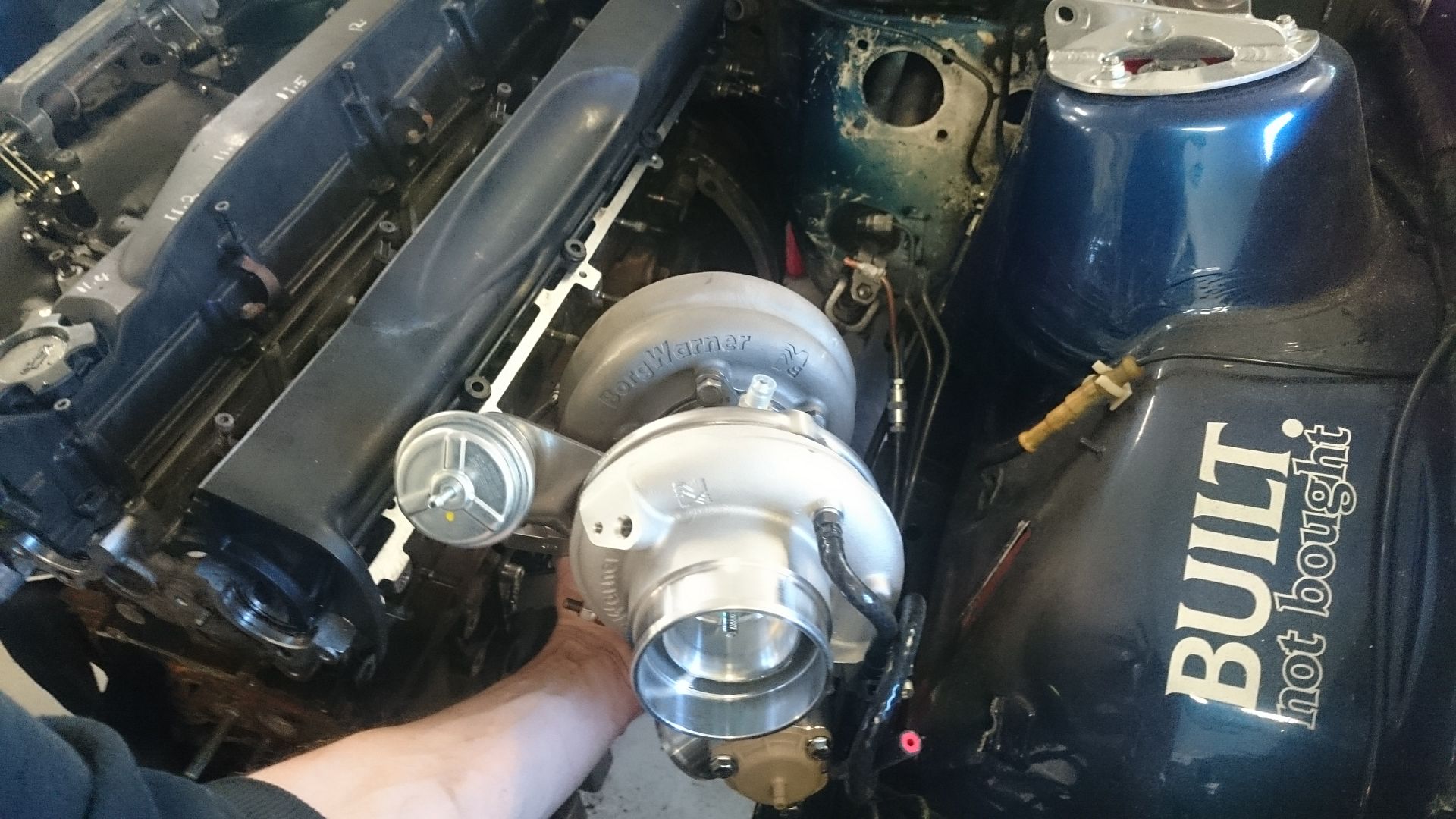
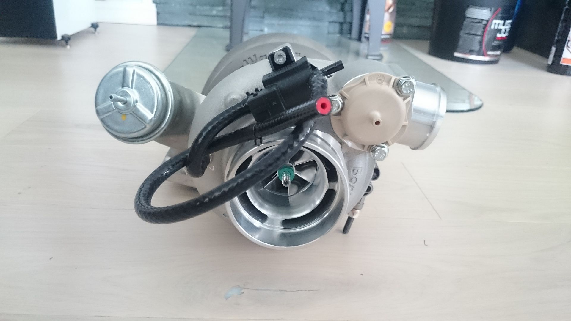
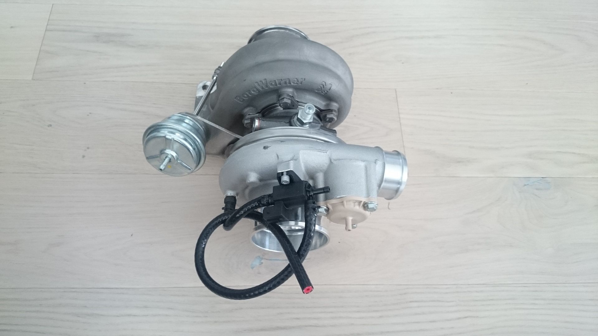
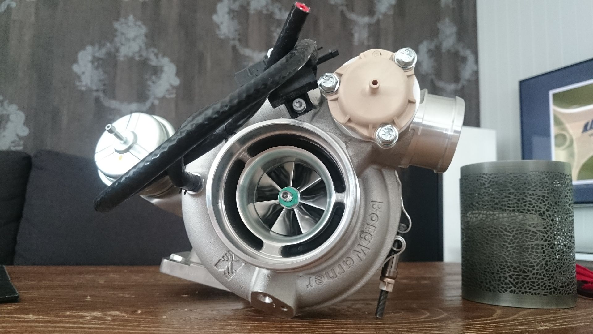
AAAAND, today, the turbo arrived!!!
Anyway, here are some photos:
Silver Project E36M3 engine mounts
Throttle cable kit:
Brake light switch:
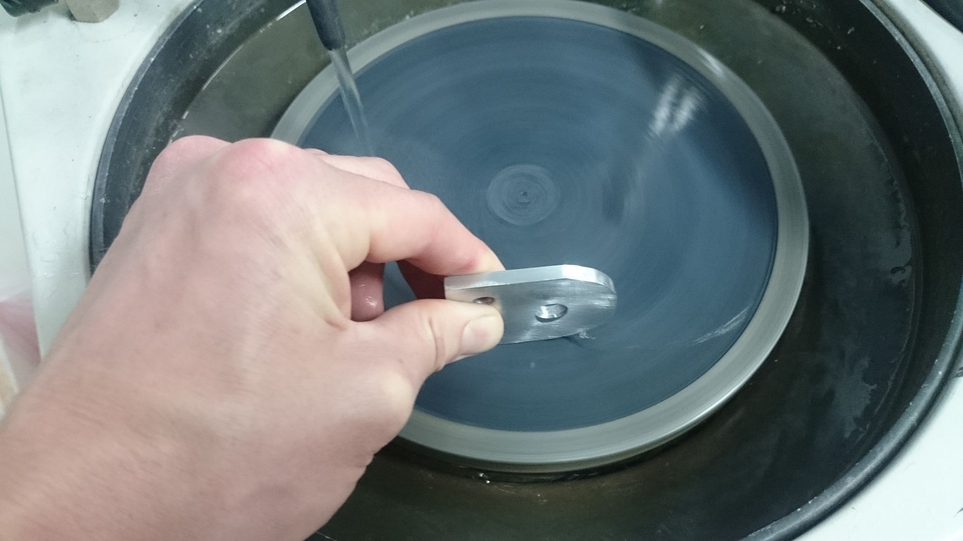
Also have been making some brackets here and there. And I like when things is looking like they are bought. So they are being sanded and polished to mirror finish. This there is for the oil cooler on top for the intercooler.
My engine mounts. Made out of steel, and just tossed some paint on them.
And the turbo. Borg Warner 7064 EFR T4 Twin Scroll .92 AR
-
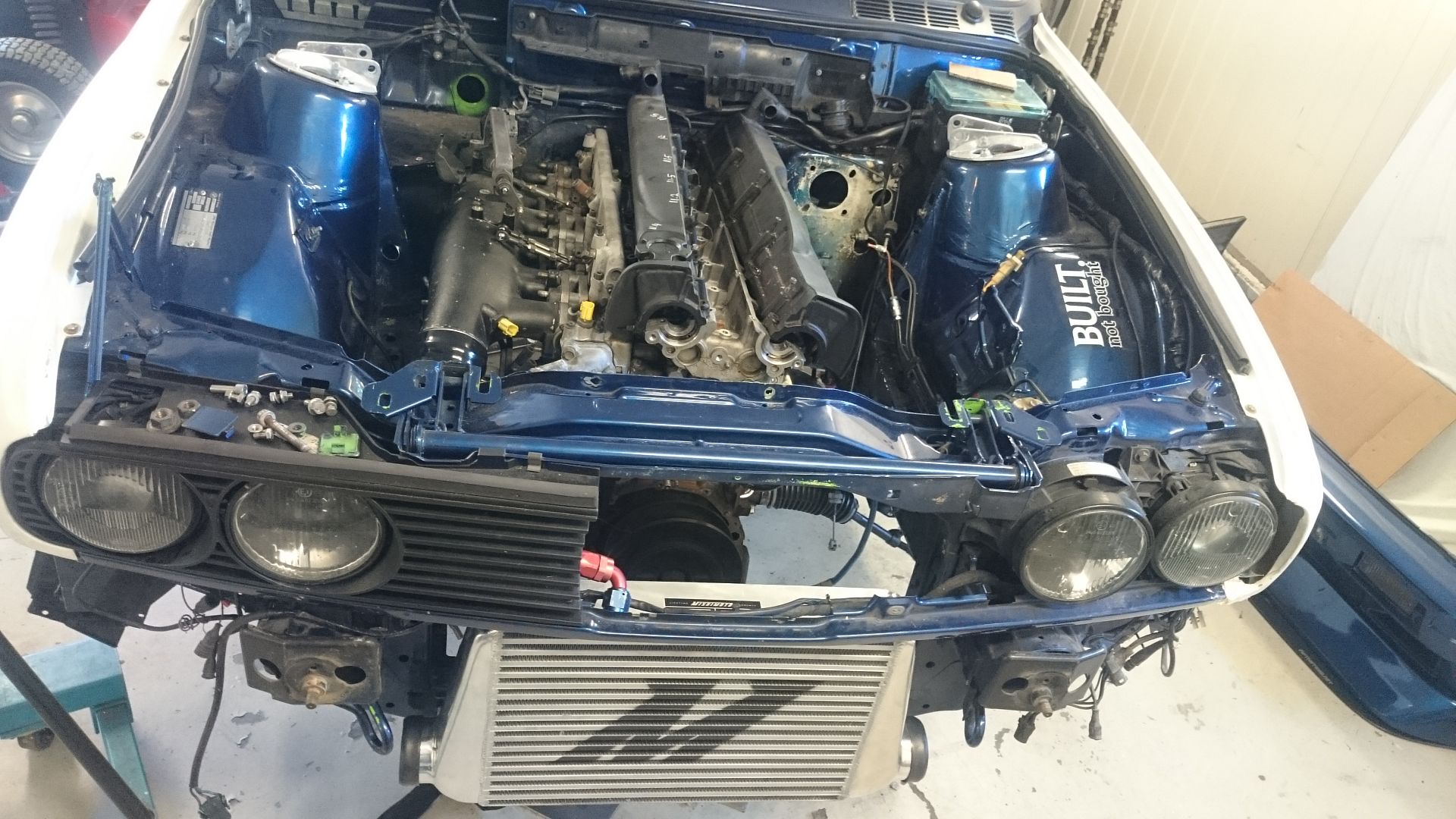
Have been working a bit on the car the last days.
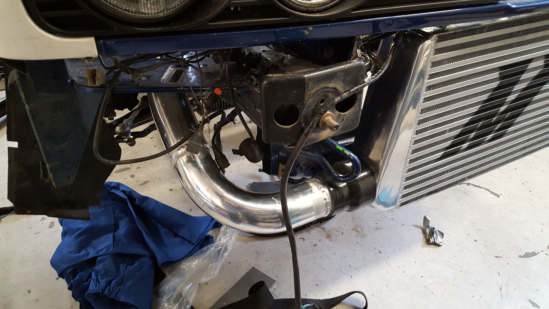
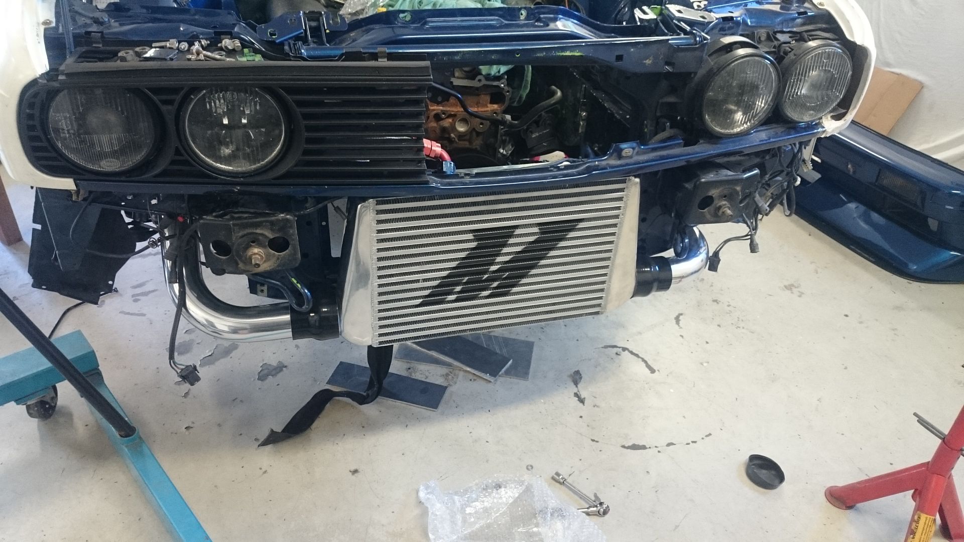
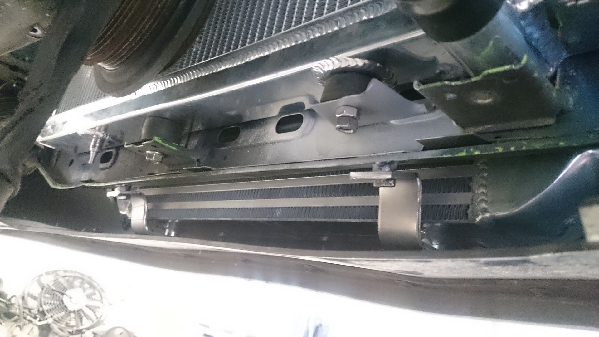
Did get the intercooler mounted, and did mock up some other bits and figured out how to do things.
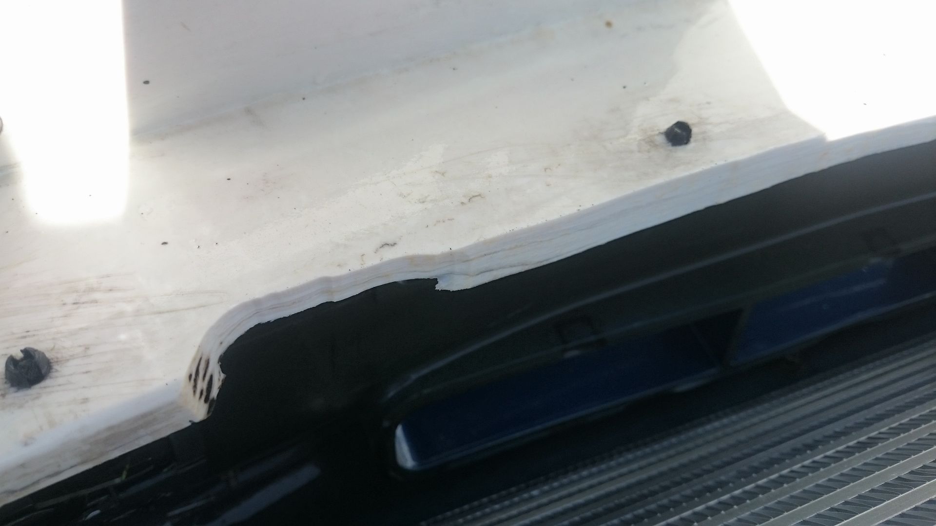
Made some room for the cooler in the front bumper here. Just used the grinder to shave off some plastic.
Had to shave off one of the points that holds the tow hook cover in place, when the tow hook is used.
Made some brackets for the intercooler, and a new lower mount for the radiator. The intercooler brackets is not finished on this picture.
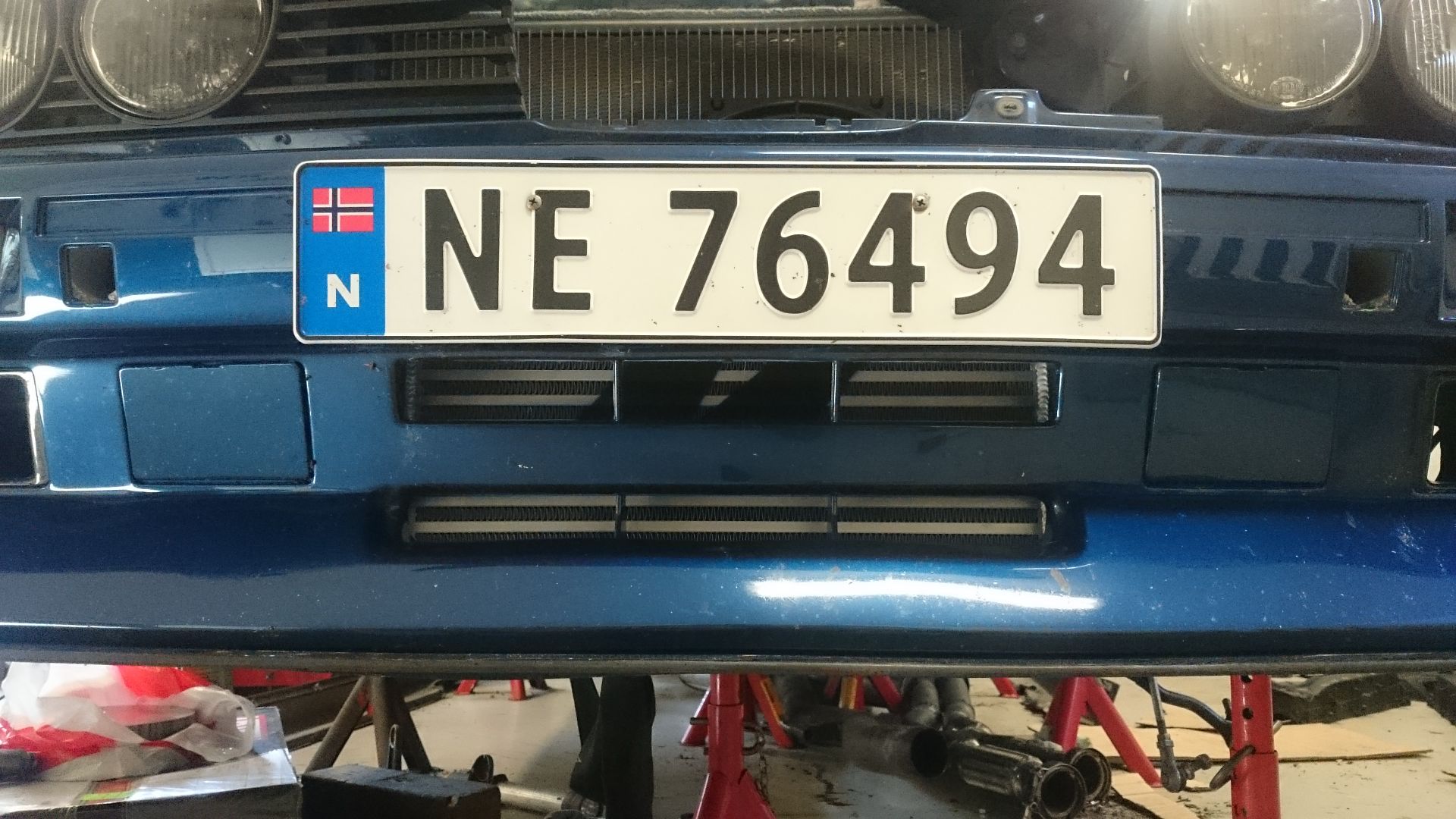
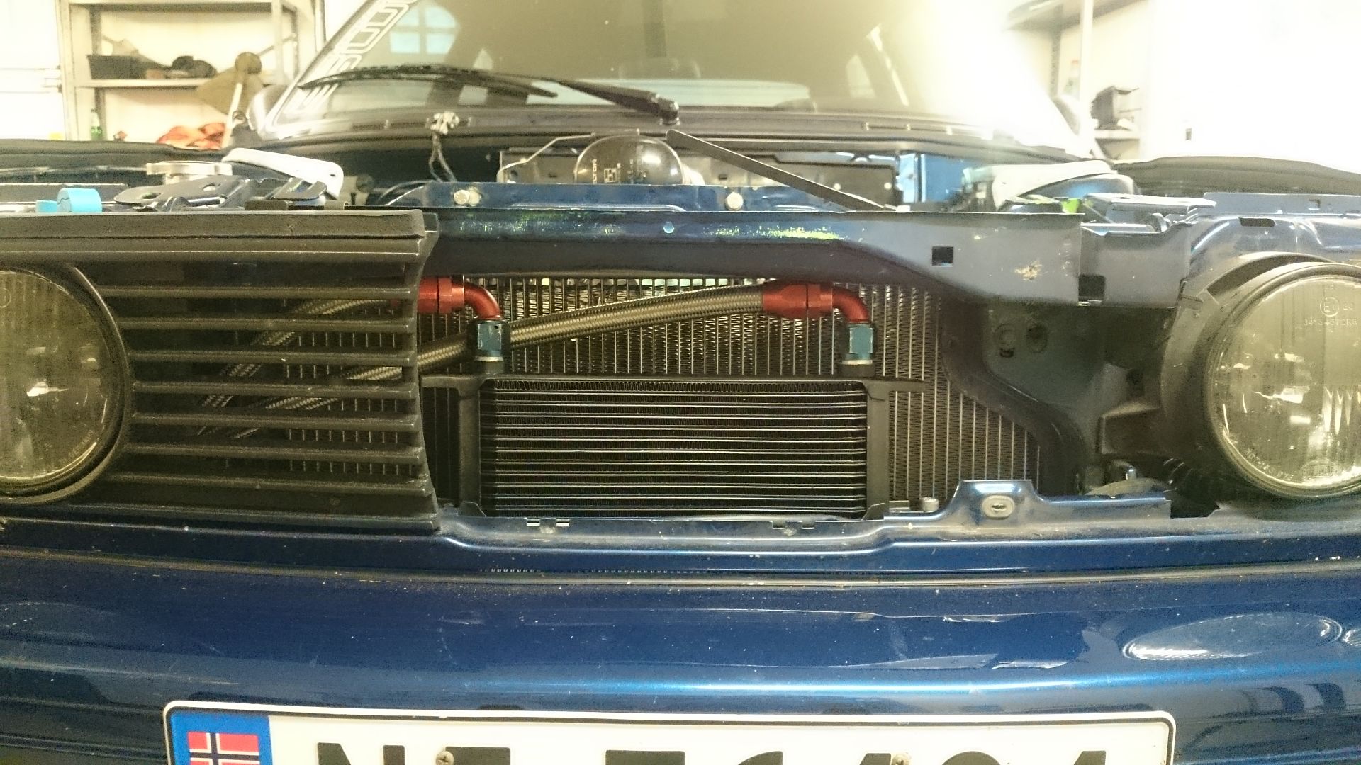
And that leaves us with this. Always wanted a intercooler behind this front.
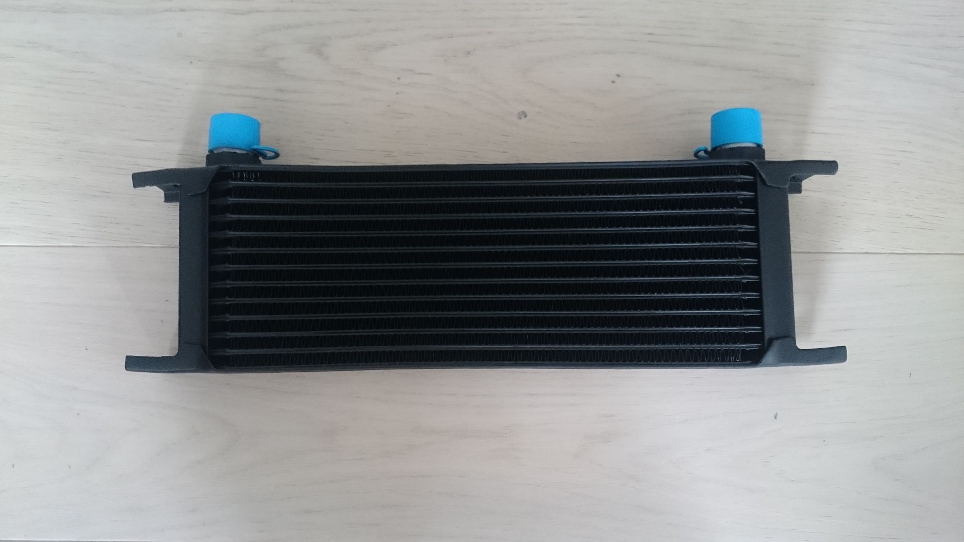
Bought a new 13 row MOCAL oil cooler. The HKS one did not fit where I wanted it.
And that MOCAL cooler will sit right on top of the intercooler.
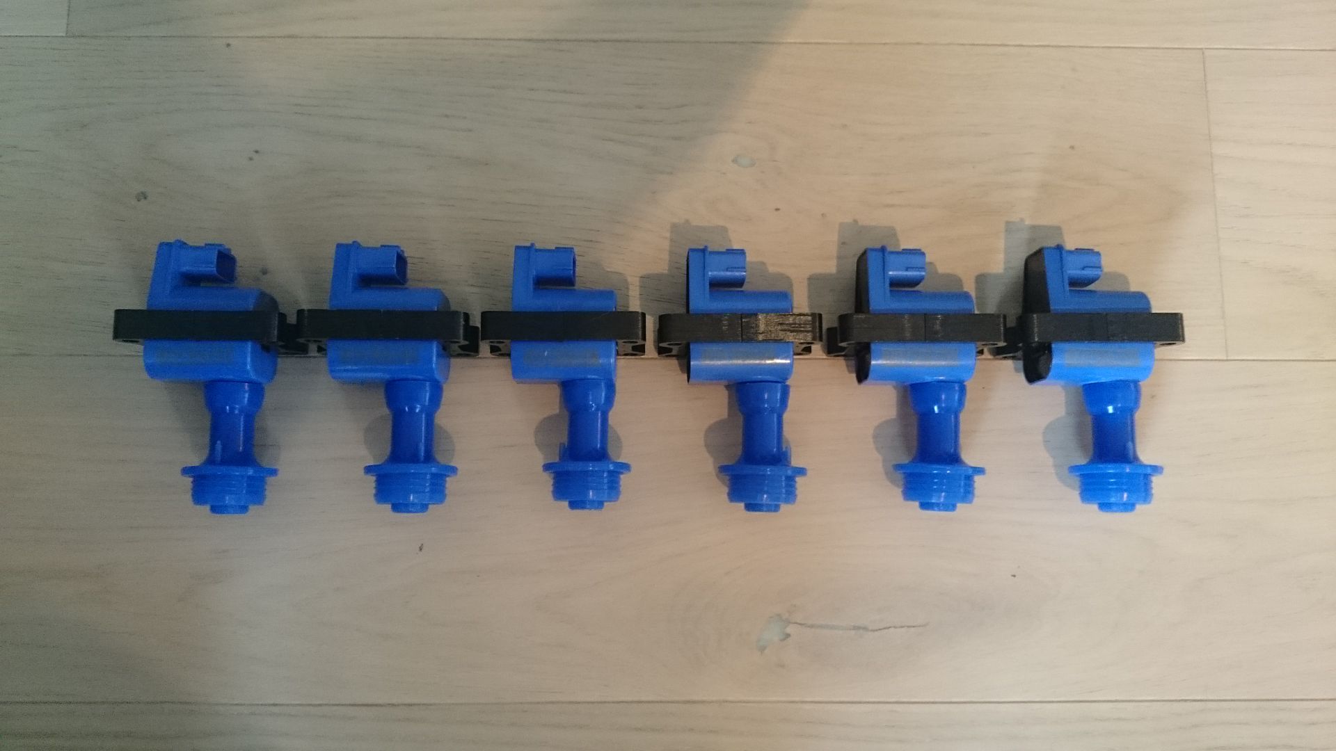
New coils did also arrive. These are named Benchmark, and have gotten a lot of good reviews. They will do for my power output anyway.
-
Parts parts parts parts
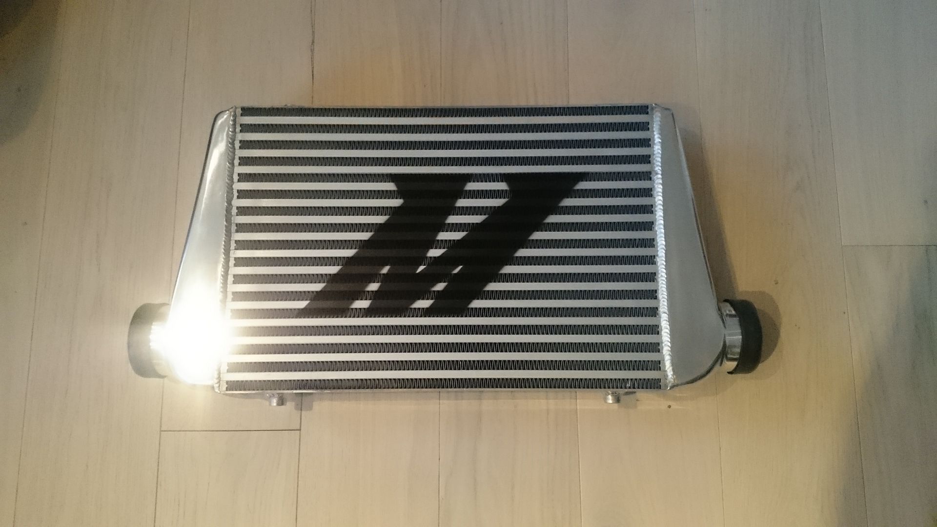
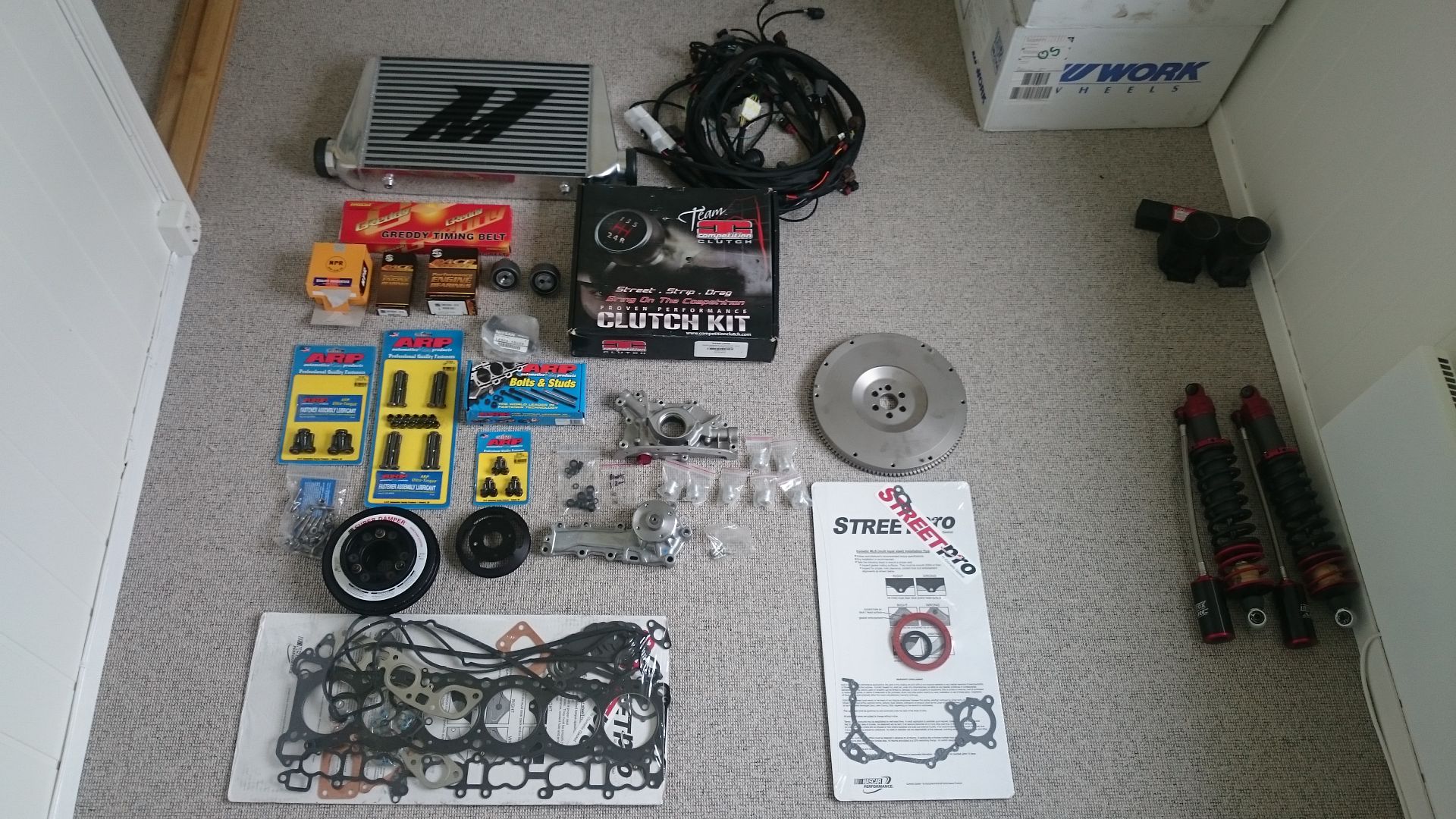
Have not done any more work on the car, just got some more parts!Mishimoto intercooler
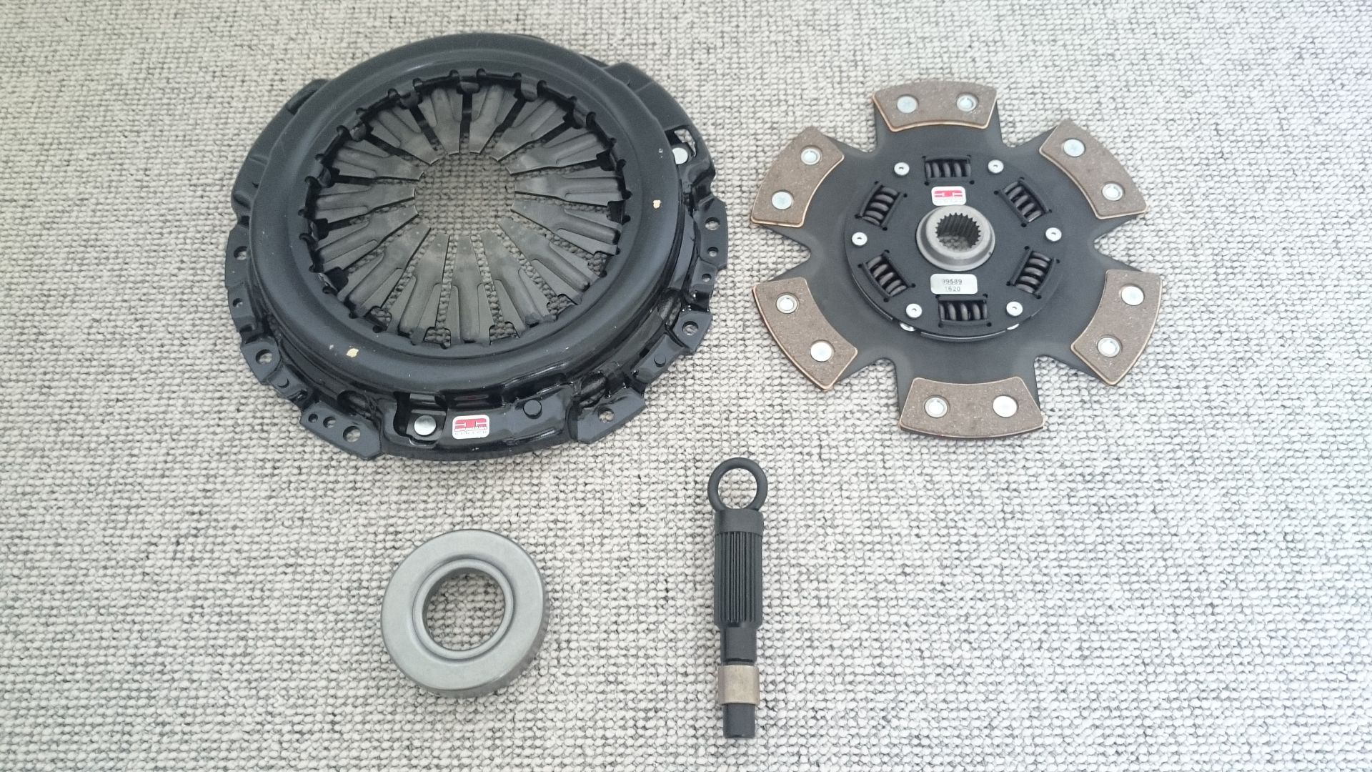
Competition Clutch stage 4
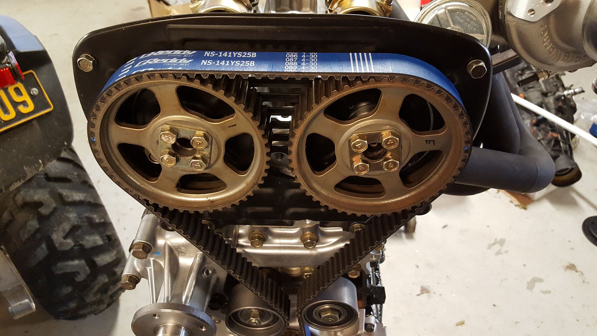
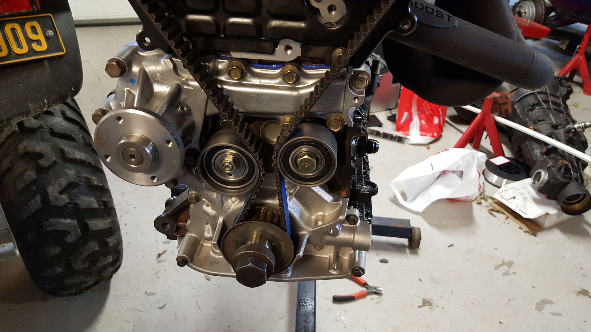
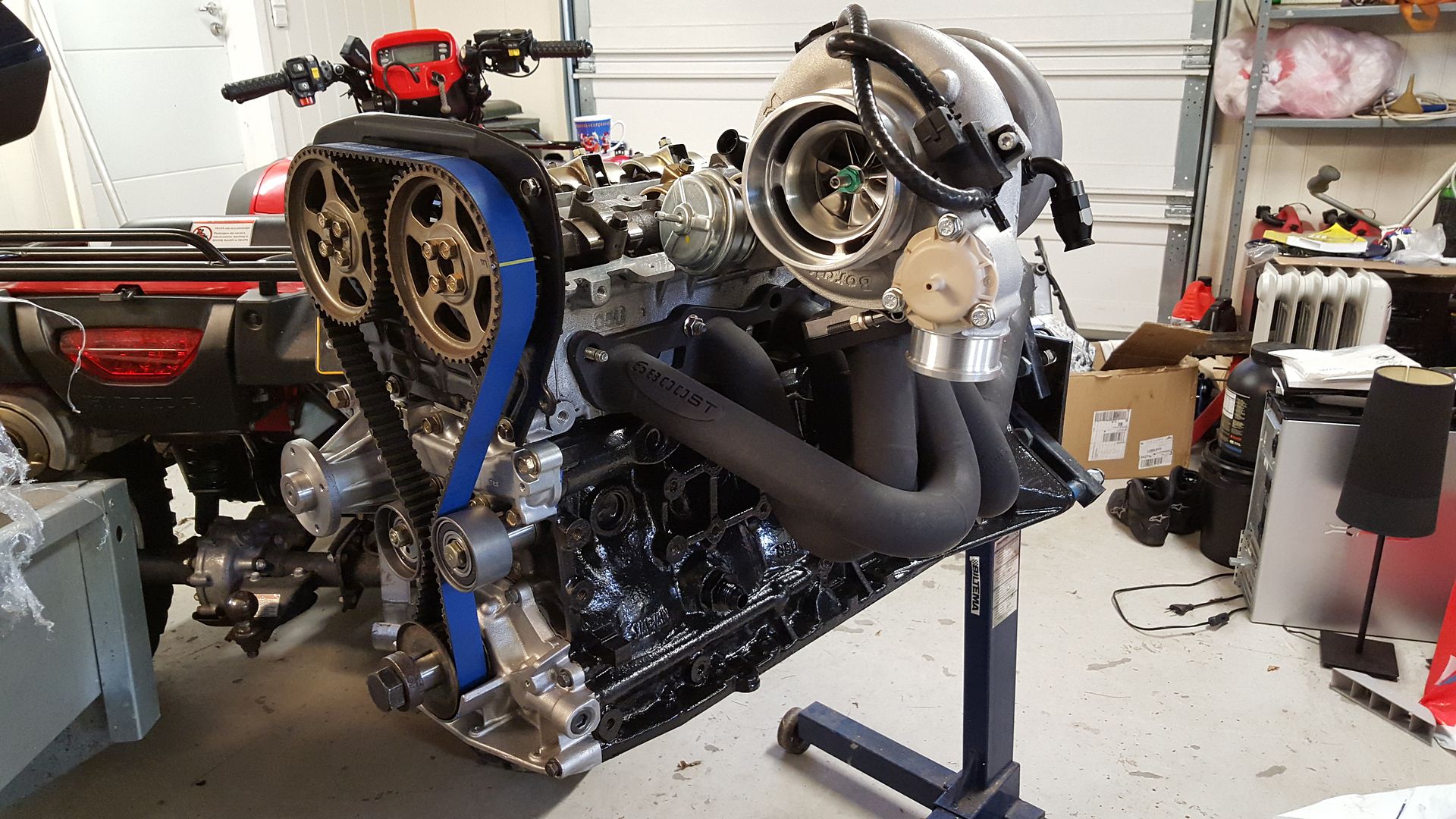
Greddy timing belt and Nissan tensioner and pulley
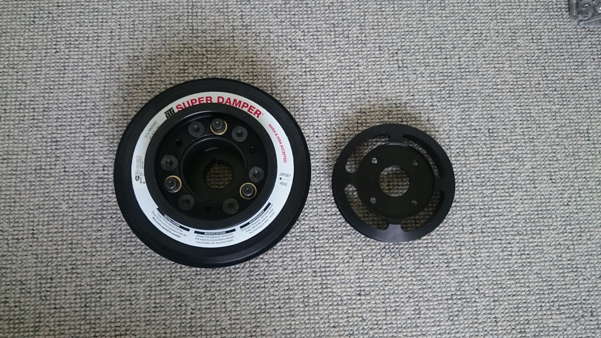
ATI Superdamper 1000hp rating
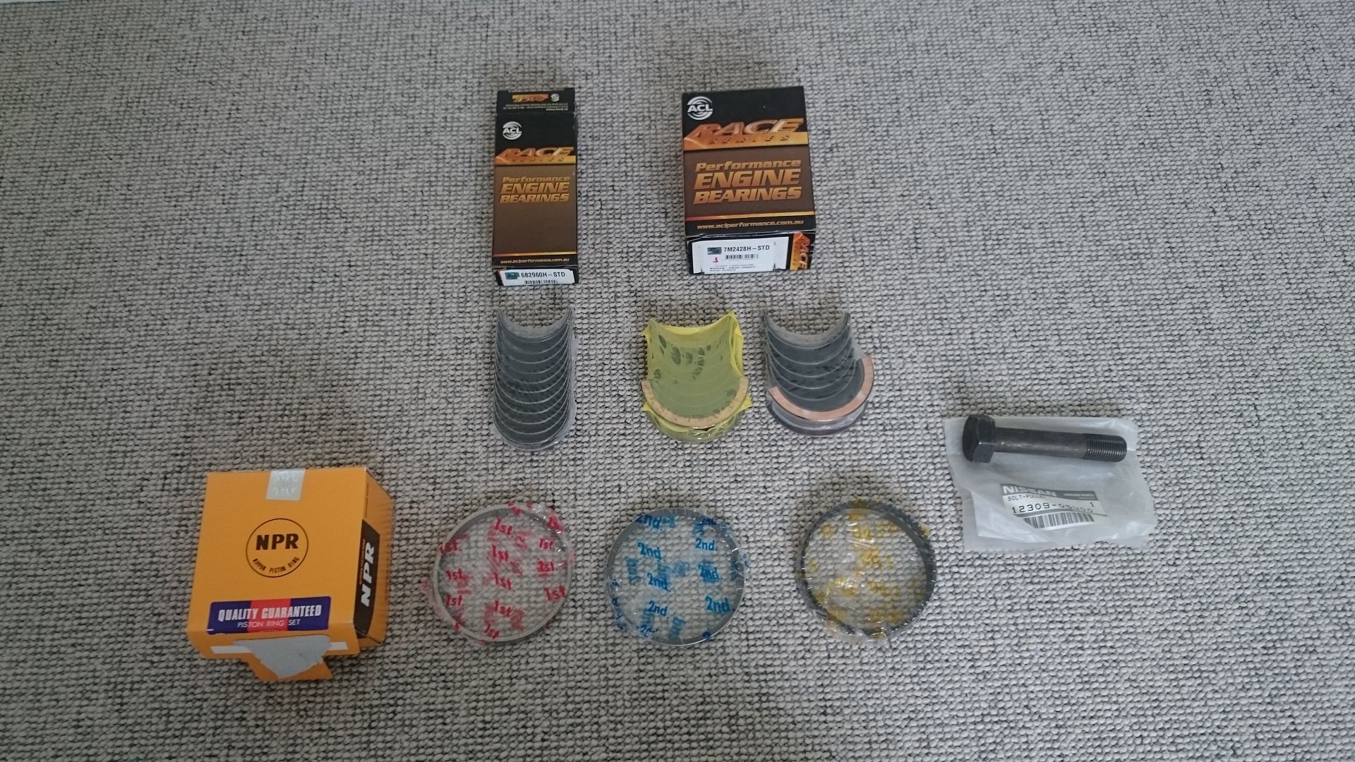
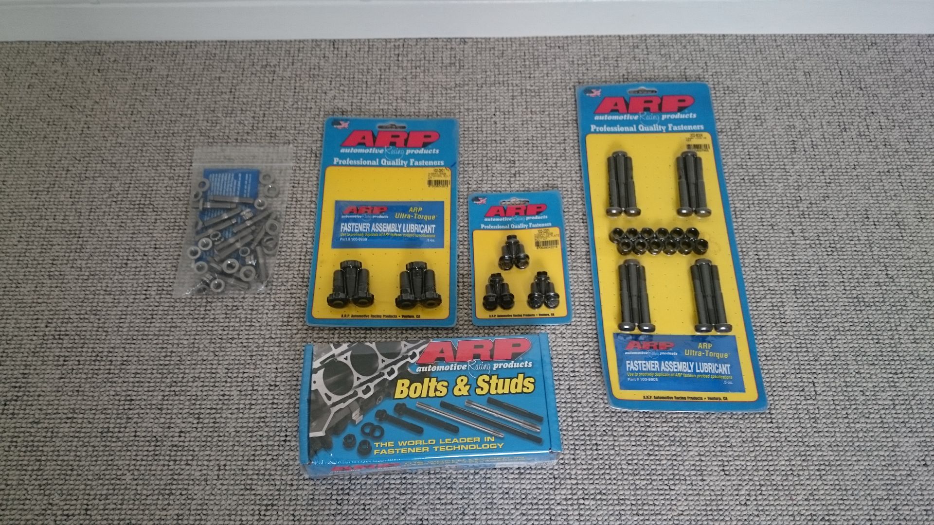
ACL Race rod- and main bearings. Nippon pistonrings
Some ARP suff. Head studs, rod bolts, flywheel bolts, pressureplate bolts and exhaust header bolts. The main studs was missing. Grrrr
And that pretty much leaves us with this, plus the used stuff that is laying in the garage
-
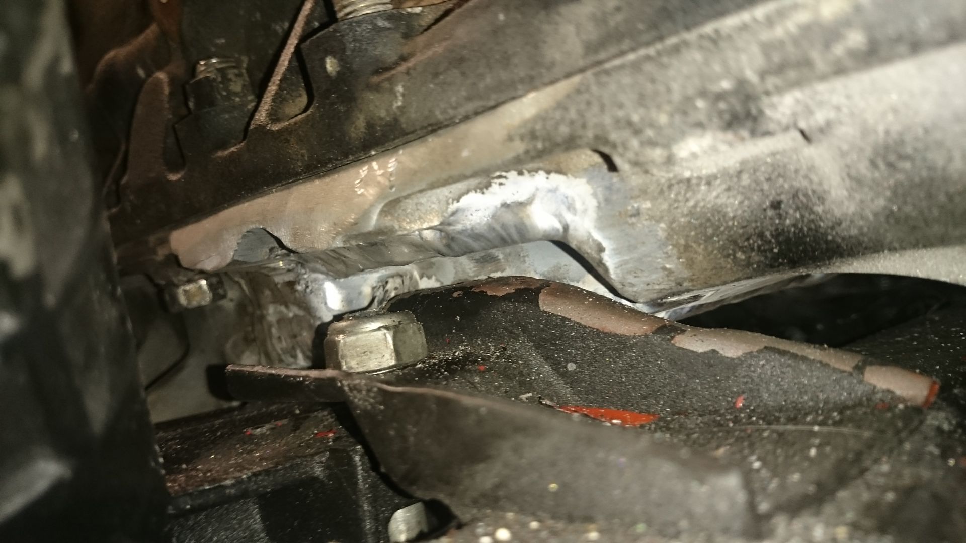
So. Have been working more on the oil pan. I have never ever tried to TIG weld aluminium before, so I had to give it a shot this time and try to learn it. I thought I got it going pretty well. It takes a lot of time compared to welding steel, that's for sure.
To start with I just cut out the oilpan to see if the engine would fit the car in the first place. Then I made some plates of 6mm aluminium and some half moons to close the holes for the driveshafts. After welding that on, The engine was crashing with the bracket for the steering rack.
In and out about 25-30 times I finally got it right with clearance and the engine placed in the middle of the car. Next step now is to start making the brackets for the engine mounts.
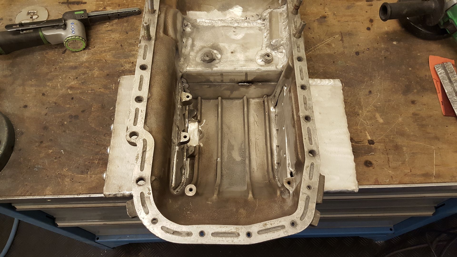
I also had to do some custom work on the JUN baffle plate. The sump became a bit smaller when I was finished, so the baffle plate would not fit as it was. So just some small mods and it was good to go.
The sump will be extended to both sides in order to swallow more oil.
I know the welds are not the art kind you usually see, but I like to do as much as I can myself and learn along the way.
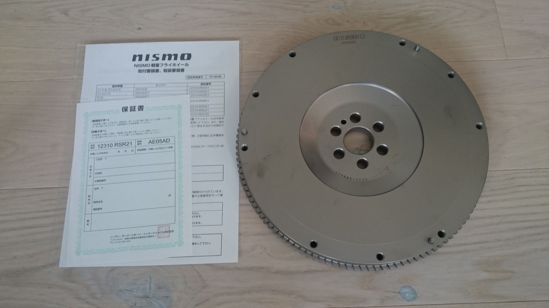
Also got some more parts in the post. First to show up was the NISMO lightweight flywheel and the Cometic MLS gasket kit. Hopefully the rest will show up later this week, as well as the Mishimoto intercooler. Looking forward to place the coolers and everything.
Made some threaded aluminium bungs, and using the fixing ears that was already on the baffle plate.
Welded and is now fitting properly.
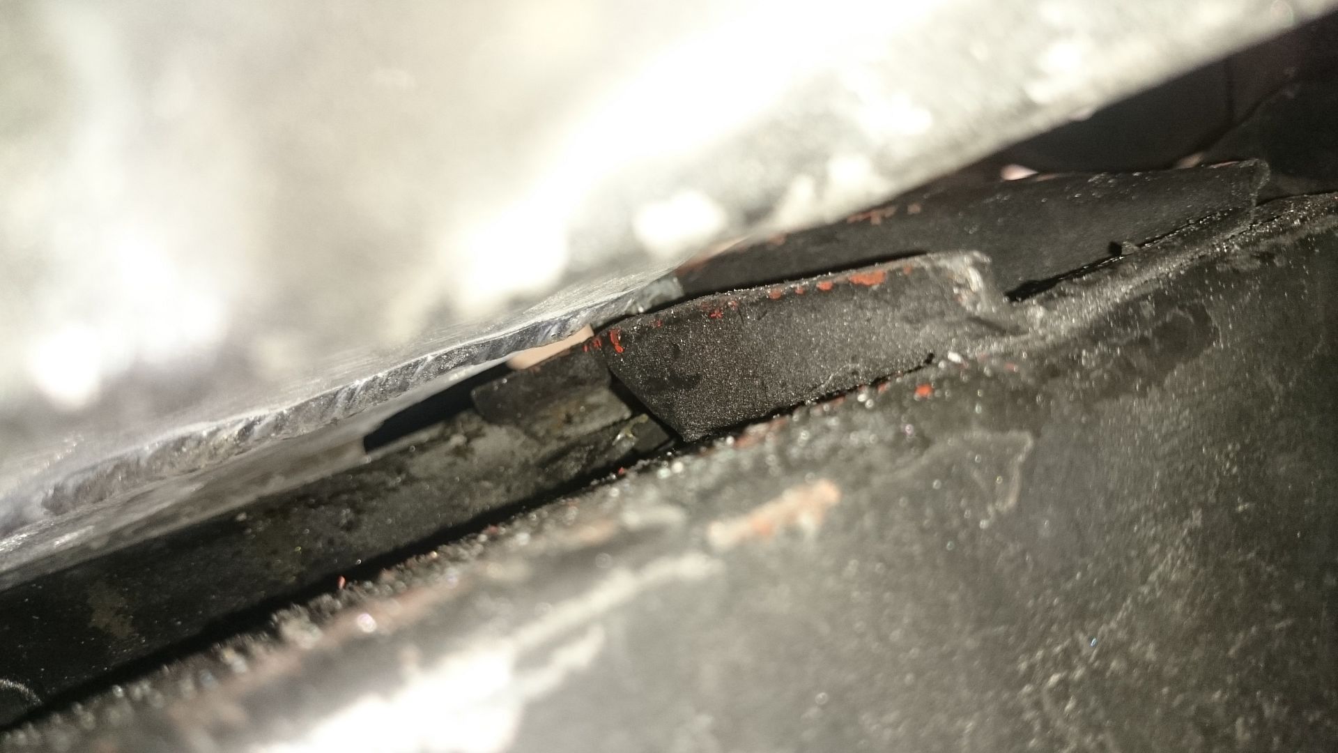
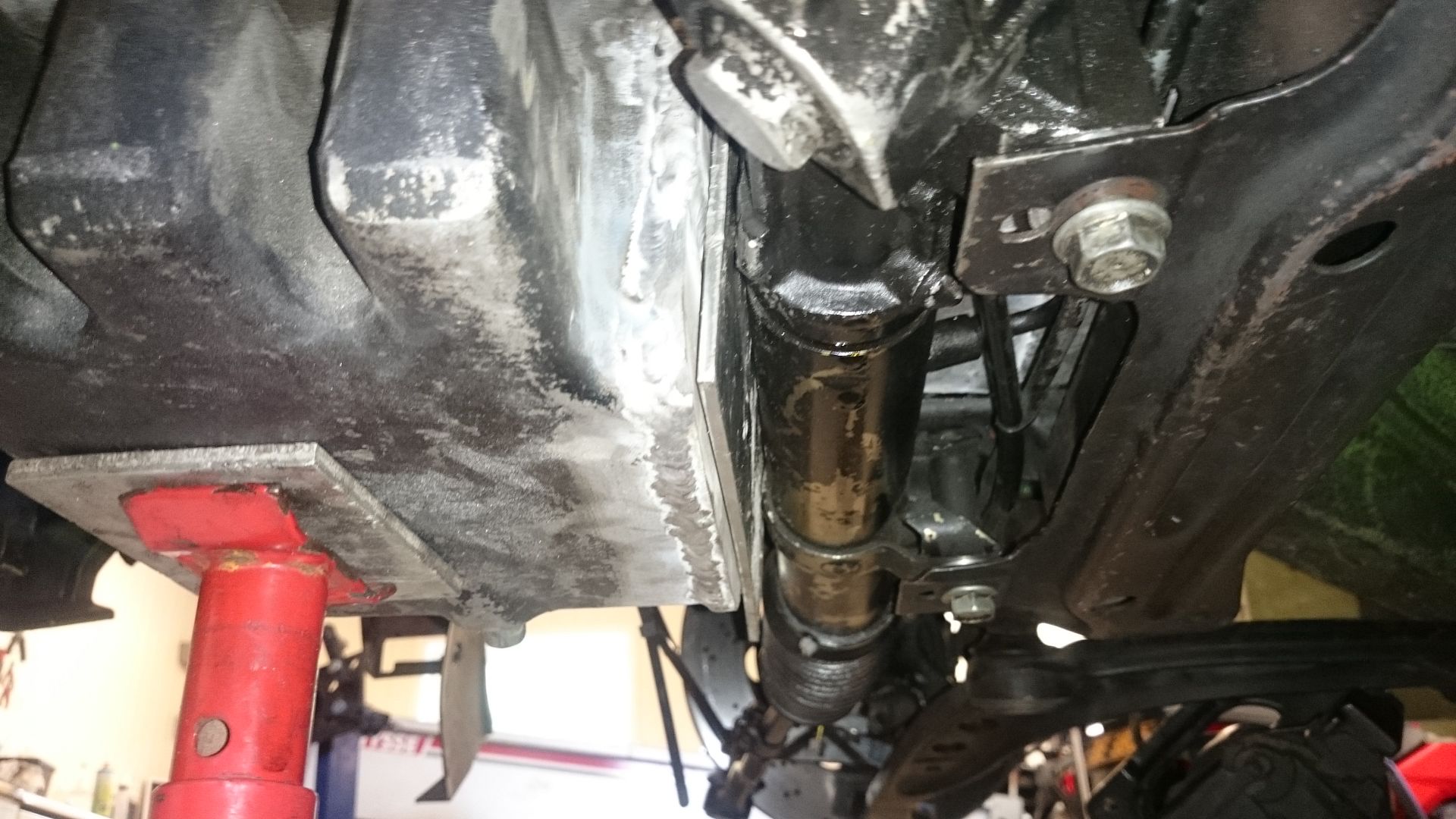
How it turned out. The dent you see is for the steering rack bracket.
Fitted in the car. Had to cut off a small bit off the bracket after this photo in order to get more clearance. When it was in the centre of the car, it was touching the bracket.
Don't mind the loose aluminium plate. It is just to have some millimeters of clearance to the steering rack.
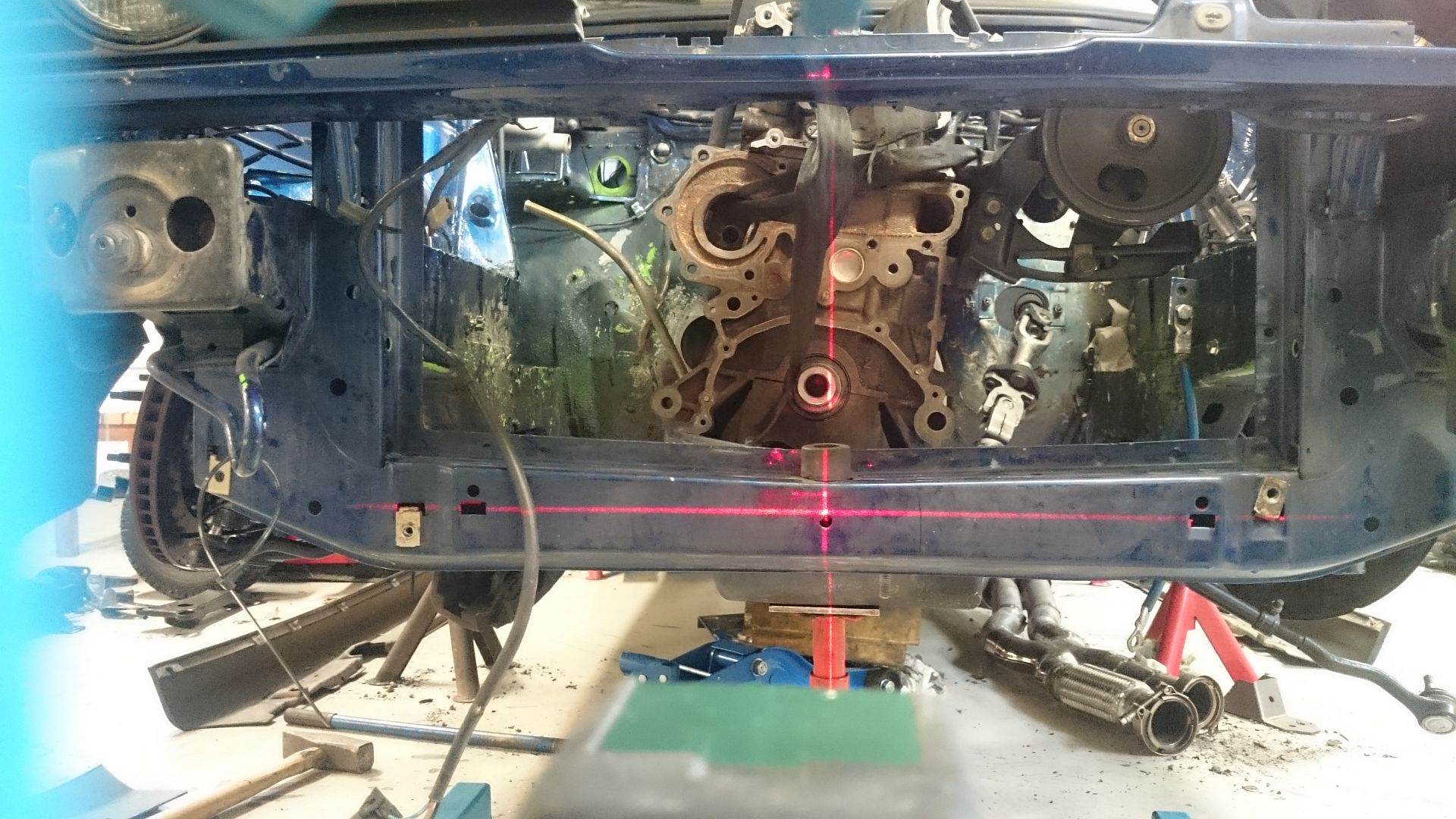
Mocking up with a laser tool. My car have been crashed on the left side at some point, so I don't think I can use a cross measurement to place the engine. Best I have is the small hole in the front box there.
Probably need to convert to electric powersteeringp pump. I see VW Lupo/Polo and some other small cars have a very descent one.
And some new parts at last.
Till next time...


Oil Control In Rb's For Circuit Drag Or Drift
in Forced Induction Performance
Posted
Because the oil that is in the catch can is not clean. At least it do not look clean.