

browny
-
Posts
486 -
Joined
-
Last visited
-
Feedback
0%
Content Type
Profiles
Forums
Events
Gallery
Media Demo
Store
Everything posted by browny
-

RB20 Cheap turbo upgrade.. few questions
browny replied to Cool Hand Luke's topic in Engines & Forced Induction
Also RB30/25 costs... This is an exaggerated example but....to claim that the rebuild cost is only $xxxx and then say "oh but i'm an engine builder and I get labour for free and parts at trade prices" is not really all that useful to the average joe who has to pay consumer prices. Maybe we should talk about a range of costs. eg DIY at the low end and "drive in drive out" at the high end -
RB20 Cheap turbo upgrade.. few questions
browny replied to Cool Hand Luke's topic in Engines & Forced Induction
sydneykid has done it and says it works great -
Thread 1 Thread 2
-
THIS LOW RPM ENGINE STALLING SAGA POSSIBLY SORTED
browny replied to BOOSTMEISTER's topic in Engines & Forced Induction
I think the ground is one. -
THIS LOW RPM ENGINE STALLING SAGA POSSIBLY SORTED
browny replied to BOOSTMEISTER's topic in Engines & Forced Induction
Pump wiring: -
THIS LOW RPM ENGINE STALLING SAGA POSSIBLY SORTED
browny replied to BOOSTMEISTER's topic in Engines & Forced Induction
Thats only the way I understand the system operates. If you want me to, I can post up a schematic of the fuel system and you can explain how it works. -
THIS LOW RPM ENGINE STALLING SAGA POSSIBLY SORTED
browny replied to BOOSTMEISTER's topic in Engines & Forced Induction
hmm thats not the way I understand it works on an RB20..... The ECU just looks to switch the power to the fuel pump via the relay so that: *When the ignition is turned on, the pump is powered for 5 sec *When the engine is cranking/running the pump is powered I think that the ecu uses a signal from the AFM to determine when the engine is cranking/running. This means that in the event of an accident where the engine stops, the ecu will turn the fuel pump off - a safety feature. The fuel pump control modulator also acts like a relay to control the voltage (and hence current) across the fuel pump by switching a resistor in and out. The resistor is located between the pump and earth and the switching is controlled by a signal from the ECU. So if you earth the pump straight to the chassis it will always receive full voltage and therefore run at full capacity whenever the ecu wants the it to run. (You might as well also remove the control modulator and resistor because this effectively short circuits their operation) If you short the relay then the modulator should still control the pump in the same way as before but you have just removed the functionality of the fuel cut safety feature. I have any of this wrong someone please correct me. -
Intercooler able to cool intake air to ambient temp?
browny replied to lambo's topic in Engines & Forced Induction
or Roy, maybe the reading is a relative temp, ie intake temp is 4 deg above ambient. That would make more sense on a day where the temp was 28deg and the reading was 18. -
Intercooler able to cool intake air to ambient temp?
browny replied to lambo's topic in Engines & Forced Induction
You are correct - gases do get cooler when they expand. Refrigerants are really just gases that have desirable condensing/evaporating temperatures/pressures. I find it very unlikely that you would ever experience this sort of effect. -
Intercooler able to cool intake air to ambient temp?
browny replied to lambo's topic in Engines & Forced Induction
Roy, that was going to be my next suggestion. Try putting both the ambient and charge air sensors on a piece of ice. Obviously both should read 0deg. -
Intercooler able to cool intake air to ambient temp?
browny replied to lambo's topic in Engines & Forced Induction
If the temperature sensor is mounted on the outside of the pipe this may not represent the temperature of the charge air accurately, especially since the pipe is HPC coated (ie insulated). -
Intercooler able to cool intake air to ambient temp?
browny replied to lambo's topic in Engines & Forced Induction
So it is measuring the temperature of the outside of the pipe - not the charge air itself? -
Intercooler able to cool intake air to ambient temp?
browny replied to lambo's topic in Engines & Forced Induction
Ronin 09 - I guess the other qualification you need is that the intercooler has to be small enough to fit into the car as well ok HPC used as a broad group of products does not just insulate stuff. There are different of coatings which are designed serve different applications, ie * Insulation * Corrosion protection * Reduce friction * Retain oil * Shed oil * Look nice In intercooler pipework applications, the coating prevents the (relatively) hot engine bay from transferring heat to the cooler charge air by acting as an insulator. So the temperature sensor you are calling ambient is not measured at a point external to the car? -
Intercooler able to cool intake air to ambient temp?
browny replied to lambo's topic in Engines & Forced Induction
HPC is just an insulator - all that means is that the pipework wont heat up and increase the temperature of the charge air. Where are the temperature sensors located? -
Intercooler able to cool intake air to ambient temp?
browny replied to lambo's topic in Engines & Forced Induction
There is probably a good explanation about why it is happening. Whatever the explantions is tho - it wont be defying the second law of thermodynamics. Where is the ambient temp measured? Where is the intake temp measured? -
Intercooler able to cool intake air to ambient temp?
browny replied to lambo's topic in Engines & Forced Induction
What about when using a water spray? That means you can start approaching the wet bulb temperature. This should theoretically be able cool it lower than the dry bulb temp (ie what is referred to as "ambient"). -
THIS LOW RPM ENGINE STALLING SAGA POSSIBLY SORTED
browny replied to BOOSTMEISTER's topic in Engines & Forced Induction
Nizmo32_Josh Why did you not just replace what appears to be a faulty relay? There would not be a relay there if there wasnt meant to be one. -
It's a temp sensor (or pyrometer) on the R32's. I will double check the wiring diagrams and ecu diagnostics I have for R32 to see how exactly its connected. From memory it didnt look like it had any ECU function and is only used for a warning light.
-
On an RB20 all the connections are on the top of the rocker covers
-
The air drawn from the intake does not neccesarily make it into the main body of the rocker cover because the two breather connections are joined. Also, i'm in the situation where I need my car engineered, AFAIK one of the stipulations is that all emissions equipment is retained.
-
Steve, The OEM piping doesnt look like it draws fresh air in anyway I want to keep this 100% legal so blocking off the PCV is not an option.
-
The silver tops definitely have the hose connecting the two covers. So if I want to be fussy and filter the fumes entering the plenum is this correct: OR should I remove the rocker cover connecting hose?
-
ok, now this is why I am confused. On my RB20 the standard PCV system appears to be slightly different: Maybe I have it drawn wrong? How would a catch can for this system be plumbed up?
-
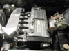
DennisRB30: Where is that brown hose coming from on the engine?
-
DennisRB30 - where on the engine does the brown hose come from in your pic?