

Announcements
-
Similar Content
-
-
Latest Posts
-
 I was 99% sure the standard one is long enough to get there, you might just have to change the throttle orientation. If not, I remember someone having used an r31 cable instead, but that is probably harder to find than r33 by now...
 -
 HELP Hey all, Is there an accelerator cable from another Nissan that can be used on the R33 GTST RB25DET with a Greddy forward facing plenum? Thanks in advance Rob
 -
 Or do we think it was installed to give 1 bar of boost max, all day, everyday?
 -
So could it be assumed it has been installed intentionally with potentially a power FC boost controller kit?
-
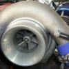 Had my rig on Matt's dyno at PITS the other day. After a few years between tunes I added a few sensors and swapped intercoolers. Result. 553hp at 26psi. Not bad for an FJ20 that was built in 2007. The problem.. It filled the overflow bottle on hard runs which leads me to believe the head gasket isn't sealing. I have a coolant pressure sensor which was reading cap pressure at 22psi and occasionally overrunning to 23/24 psi on deceleration after a pull. It was not spiking. It has arp2000 head studs and a cometic gasket. As its been 18 years in service, I pulled the engine out and head off. Everything looks good but we obviously have an issue. Where I'm at.. Years ago I had the same issue, I checked the stud tension and they were all over the place. Some at 60 to 70 and some up near 90. I nipped them all to 100ft lbs and this stopped the water push until now. I believe this compromised the gasket back then. What do I do? 2 options are.. 1) I bought arp 625+s, which I could put in with a new gasket. Thinking Kameari this time, reassemble and try again. 2) strip the block, get fire rings machined in with copper gasket and try that. I do not want to push it more than 28 to 30psi. I think the turbo will be out by then anyway. (G30-770). My other concern is the long term ability of a copper head gasket. Are they streetable for years? I feel like a new gasket with the new studs will probably suffice, but I don't know. Any thoughts welcome and advice on copper gaskets and fire rings. Thanks!
-


Recommended Posts
Create an account or sign in to comment
You need to be a member in order to leave a comment
Create an account
Sign up for a new account in our community. It's easy!
Register a new accountSign in
Already have an account? Sign in here.
Sign In Now