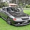
R32 Heavy Power Steering - How To Disable Speed Variable Assist Steering And Control Power Assistance Level.
Announcements
-
Similar Content
-
Latest Posts
-
Yeah, but look at the margin in viscosity between the 40 and the 60 at 125°C. It is not very large. It is the difference between 7 and 11 cP. Compare that to the viscosity at only 90°C. The viscosity axis is logarithmic. The numbers at 90 are ~15 and ~35. That is about half for the 40 wt oil and <half for the 60. You give up viscosity EXPONENTIALLY as temperature rises. Literally. That is why I declare thicker oil to be a bandaid, and a brittle one at that. Keep the oil temperature under about 110°C and you should be better off. Having said all of that, which remains true as a general principle, if you have indeed lost enough oil from the sump that the pump was seeing slightly aerated oil, then all bets are off. That would of course cause oil pressure to collapse. And 35 psi is a collapse given what you were doing to the engine. Especially if the oil was that hot and viscosity had also collapsed. And I would put money on rod or main bearings being the source of the any noise that registered as knock. Hydraulic lifters should be able to cope with the hotter oil and lower pressure enough to prvent too much high frequency noise, although I am willing to admit it could be the source.
-
Thanks for the reply mate. Well I really hope its a hose then not engine out job
-
But.... the reason I want to run a 60 weight is so at 125C it has the same viscosity as a 40 weight at 100C. That's the whole reason. If the viscosity changes that much to drop oil pressure from 73psi to 36psi then that's another reason I should be running an oil that mimics the 40 weight at 100C. I have datalogs from the dyno with the oil pressure hitting 73psi at full throttle/high RPM. At the dyno the oil temp was around 100-105C. The pump has a 70psi internal relief spring. It will never go/can't go above 70psi. The GM recommendation of 6psi per 1000rpm is well under that... The oil sensor for logging in LS's is at the valley plate at the back of the block/rear of where the heads are near the firewall. It's also where the knock sensors are which are notable for 'false knock'. I'm hoping I just didn't have enough oil up top causing some chatter instead of rods being sad (big hopium/copium I know) LS's definitely heat up the oil more than RB's do, the stock vettes for example will hit 300F(150C) in a lap or two and happily track for years and years. This is the same oil cooler that I had when I was in RB land, being the Setrab 25 row oil cooler HEL thing. I did think about putting a fan in there to pull air out more, though I don't know if that will actually help in huge load situations with lots of speed. I think when I had the auto cooler. The leak is where the block runs to the oil cooler lines, the OEM/Dash oil pressure sender is connected at that junction and is what broke. I'm actually quite curious to see how much oil in total capacity is actually left in the engine. As it currently stands I'm waiting on that bush to adapt the sender to it. The sump is still full (?) of oil and the lines and accusump have been drained, but the filter and block are off. I suspect there's maybe less than 1/2 the total capacity there should be in there. I have noticed in the past that topping up oil has improved oil pressure, as reported by the dash sensor. This is all extremely sketchy hence wanting to get it sorted out lol.


Recommended Posts
Create an account or sign in to comment
You need to be a member in order to leave a comment
Create an account
Sign up for a new account in our community. It's easy!
Register a new accountSign in
Already have an account? Sign in here.
Sign In Now