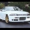
R33 GTST Tail Light Wiring...
Announcements
-
Similar Content
-
Latest Posts
-
Hello, sorry for being late to join the discussion, but my clock just died on me. Ive tried to look at Michaels digital clock repair.docx and it doesnt work maybe the file has expired. Please let me know if you can re upload it or take some youtube videos to show us how to get the clock installed? thanks
-
By MissMintyR33 · Posted
I thought that might be the case, thats what I'll start saving for. Thanks for the info -
Ps i found the below forum and it seems to be the same scenario Im dealing with. Going to check my ECU coolant temp wire tomorrow From NICOclub forum: s1 RB25det flooding at start up Thu Apr 11, 2013 7:23 am I am completely lost on this. Car ran perfectly fine when I parked it at the end of the year. I took the engine out and painted the engine bay, and put a fuel cell with an inline walbro 255 instead of the in tank unit I had last year. After reinstalling everything, the engine floods when the fuel pump primes. if i pull the fuel pump fuse it'll start, and as soon as I put the fuse back in it starts running ridiculously rich. I checked the tps voltage, and its fine. Cleaned the maf as it had some dust from sitting on a shelf all winter, fuel pressure is correct while running, but wont fire until there is less than 5psi in the lines. The fuel lines are run correctly. I have found a few threads with the same problem but no actual explanation of what fixed it, the threads just ended. Any help would be appreciated. Rb25det s1 walbro255 fuel pump nismo fpr holset hx35 turbo fmic 3" exhaust freddy intake manifold q45tb q45 maf Re: s1 RB25det flooding at start up Fri Apr 12, 2013 5:07 am No, I didn't. I found the problem though. There was a break in one of the ecu coolant temp sensor wires. Once it was repaired it fired right up with no problems. I would have never thought a non working coolant temp sensor would have caused such an issue.
-
Hi sorry late reply I didnt get a chance to take any pics (my mechanics on the other side of the city) but the plugs were fouled from being too rich. I noticed the MAF wasn't genuine, so I replaced it with a genuine green label unit. I also swapped in a different ignitor, but the issue remains. I've narrowed it down a bit now: - If I unplug and reconnect the fuel lines and install fresh spark plugs, the car starts right up and runs perfectly. Took it around the block with no issues - As soon as I shut it off and try to restart, it won't start again - Fuel pressure while cranking is steady around 40 psi, injectors have good spray, return line is clear, and the FPR vacuum is working. It just seems like it's getting flooded after the first start I unplugged coolant sensors to see if its related to ECU flooding but that didnt make a difference. Im thinking its related to this because this issue only started happening after fixing coolant leaks and replacing the bottom part of the stock manifolds coolant pipe. My mechanic took off the inlet to get to get to do these repairs. My mechanics actually just an old mate who's retired now so ill be taking it to a different mechanic who i know has exp with RBs to see if they find anything. If you have any ideas please send em lll give it a try. Ive tried other things like swapping the injectors, fuel rail, different fuel pressure regs, different ignitor, spark plugs, comp test and MAF but the same issue persists.
-
My return flow is custom and puts the return behind the reo, instead of at the bottom. All my core is in the air flow, rather than losing some of it up behind the reo. I realise that the core really acts more as a spiky heatsink than as a constant rate heat exchanger, and that therefore size is important.... but mine fits everything I needed and wanted without having to cut anything, and that's worth something too. And there won't be a hot patch of core up behind the reo after every hit, releasing heat back into the intake air.
-


Recommended Posts
Create an account or sign in to comment
You need to be a member in order to leave a comment
Create an account
Sign up for a new account in our community. It's easy!
Register a new accountSign in
Already have an account? Sign in here.
Sign In Now