
What other plenums besides Greddy/Trust?
Announcements
-
Similar Content
-
-
Latest Posts
-

By myrbgivesmeheadaches · Posted
Did this end up working? Did you take some pictures? -
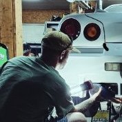
 And finally, the front lower mount. It was doubly weird. Firstly, the lower mount is held in with a bracket that has 3 bolts (it also acts as the steering lock stop), and then a nut on the shock lower mount itself. So, remove the 3x 14mm head bolts , then the 17mm nut that holds the shock in. From there, you can't actually remove the shock from the lower mount bolt (took me a while to work that out....) Sadly I don't have a pic of the other side, but the swaybar mounts to the same bolt that holds the shock in. You need to push that swaybar mount/bolt back so the shock can be pulled out past the lower control arm. In this pic you can see the bolt partly pushed back, but it had to go further than that to release the shock. Once the shock is out, putting the new one in is "reverse of disassembly". Put the top of the shock through at least one hole and put a nut on loosely to hold it in place. Put the lower end in place and push the swaybar mount / shock bolt back in place, then loosely attach the other 2 top nuts. Bolt the bracket back in place with the 14mm head bolts and finally put the nut onto the lower bolt. Done....you have new suspension on your v37!
 -
And now to the front. No pics of the 3 nuts holding the front struts on, they are easy to spot. Undo 2 and leave the closest one on loosely. Underneath we have to deal with the wiring again, but this time its worse because the plug is behind the guard liner. You'll have to decide how much of the guard liner to remove, I undid the lower liner's top, inside and lower clips, but didn't pull it full off the guard. Same issue undoing the plug as at the rear, you need to firmly push the release clip from below while equally firmly gripping the plug body and pulling it out of the socket. I used my fancy electrical disconnect pliers to get in there There is also one clip for the wiring, unlike at the rear I could not get behind it so just had to lever it up and out.....not in great condition to re-use in future.
-
Onto the rear lower shock mount. It's worth starting with a decent degrease to remove 10+ years of road grime, and perhaps also spray a penetrating oil on the shock lower nut. Don't forget to include the shock wiring and plug in the clean.... Deal with the wiring first; you need to release 2 clips where the wiring goes into the bracket (use long nose pliers behind the bracket to compress the clip so you can reuse it), and the rubber mount slides out, then release the plug. I found it very hard to unplug, from underneath you can compress the tab with a screwdriver or similar, and gently but firmly pull the plug out of the socket (regular pliers may help but don't put too much pressure on the plastic. The lower mount is straightforward, 17mm nut and you can pull the shock out. As I wasn't putting a standard shock back in, I gave the car side wiring socket a generous gob of dialectric grease to keep crap out in the future. Putting the new shock in is straightforward, feed it into at least 1 of the bolt holes at the top and reach around to put a nut on it to hold it up. Then put on the other 2 top nuts loosely and put the shock onto the lower mounting bolt (you may need to lift the hub a little if the new shock is shorter). Tighten the lower nut and 3 upper nuts and you are done. In my case the BC Racing shocks came assembled for the fronts, but the rears needed to re-use the factory strut tops. For that you need spring compressors to take the pressure off the top nut (they are compressed enough when the spring can move between the top and bottom spring seats. Then a 17mm ring spanner to undo the nut while using an 8mm open spanner to stop the shaft turning (or, if you are really lucky you might get it off with a rattle gun).
-
You will now be able to lift the parcel shelf trim enough to get to the shock cover bolts; if you need to full remove the parcel shelf trim for some reason you also remove the escutcheons around the rear seat release and you will have to unplug the high stop light wiring from the boot. Next up is removal of the bracket; 6 nuts and a bolt Good news, you've finally got to the strut top! Remove the dust cover and the 3 shock mount nuts (perhaps leave 1 on lightly for now....) Same on the other side, but easier now you've done it all before
-


Recommended Posts
Create an account or sign in to comment
You need to be a member in order to leave a comment
Create an account
Sign up for a new account in our community. It's easy!
Register a new accountSign in
Already have an account? Sign in here.
Sign In Now