Jump to content
SAU Community

Recommended Posts

  • Replies 110
  • Created
  • Last Reply

Top Posters In This Topic

IMG_0480.jpg

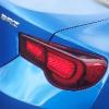
RIP eyelid - 2004 - 2010. She served me well, stayed on the car at 200kmp/h, never once looked like falling off. Then between home and the carwash at 70kmp/h, she departed this world.

Took an hour to get the other one off and clean all the sikaflex off both headlights. Good as new:

IMG_0484.jpg

Updated specs while I'm at it:

Engine/Driveline:

- Engineered/VASS certified JDM Avenir PNW10 SR20DET (2L Turbo) conversion from stock GA16DE (1.6L N/A), custom wiring harness, air-con removed.

- Avenir ECU re-mapped by Dr Drift

- Nismo 740cc injectors

- Z32 Airflow Meter with Bosch plug

- Silvia S15 Fuel Pump

- HKS EVC 6 Electronic Boost Controller

- HKS Oil Cap

- Nismo Radiator Cap

- SR20DE engine mounts pressed with solid inserts

- 600x300x76 JustJap Front Mount Intercooler, custom mandrel-bent Stainless Steel piping

- Go Fast Bits StealthFX Plumb-back/Atmo Blow Off Valve (Black) - recirculates to pod box for legal reasons

- Custom Aluminium Pod Box with 3A Racing Pod Filter, Metal Intake Pipe, battery moved elsewhere in engine bay to suit

- GT2860RS turbo (.64 housing) with modified actuator bracket and rod

- Pulsar RNN14 GTi-R Exhaust Manifold

- Longer Manifold Studs

- Liverpool Exhaust 10mm Manifold Spacer

- 3" full Stainless Steel Exhaust, Stainless Steel straight-through Muffler with Droopy Chrome Tip

- CES Split GTi-R Dump Pipe HPC-coated silver

- CES Metal Substrate Catalytic Converter

- Pulsar NX-R manual gearbox completely rebuilt with:

*PAR RS5F32A 1st~4th straight cut synchromesh gearset

*PAR RS5F32 Crown Wheel & Pinion Shaft 4.08 ratio

*GC Corp sprung centre 24 spline clutch kit

*New Differential Bearings

*Nismo 1.5 Way LSD

- Custom Pulsar RNN14 GTi-R & N16 hydraulic clutch conversion

Suspension & Brakes:

- Tein Super Street Coilovers with Pillow-Ball Upper Mounts

- Tein Electronic Damper Force Control (EDFC) on each strut

- Whiteline Blade Adjustable Rear Swaybar

- Whiteline Adjustable Front Strut Brace

- Sentra B14/200sx Adjustable Rear Strut Brace

- Pulsar N15 SSS 28mm Front Swaybar

- Whiteline Front Swaybar D-Bushes

- Whiteline Front Swaybar End-link Bushes

- Whiteline Steering Rack Bushes

- Pulsar RNN14 GTi-R Front Calipers (AD22VF) sprayed gold

- Bendix Advance Brake Pads (front)

- DBA Slotted Rotors (front)

- Pulsar N15 SSS Rear Disc Brake rear axle conversion (calipers sprayed gold)

- Unknown pads and rotors (rear)

- Modified stock Brake Master Cylinder

Body Modifications:

- Pulsar N15 S1 SSS Front Bumper (middle insert cut out for FMIC)

- Topstage S1 Lip

- ASV N15 (VZ-R Copy) Side Skirts

- ASV N15 (VZ-R Copy) Sedan Rear Pods

- JDM Pulsar N15 Lucino Grille

- JDM Pulsar N15 GT Bootlid with high-mount brake light mounted in the spoiler

- De-stickered and de-badged bootlid

- Full respray in custom White with House of Kolor Ice Turquoise Pearl

- Black Bonnet & Grille with House of Kolor Ice Turquoise Pearl

- Colour-coded door handles and mirrors

Interior:

- Pulsar N15 S2 SSS Steering Wheel

- 1Kg Dry Chemical Fire Extinguisher mounted in the passenger foot well

- Defi DIN cluster mounted in DIN spot under Air-Con/Heater Controls, head unit relocated to bottom DIN slot

- Defi Racer Series Boost Gauge mounted to drivers side A-Pillar

- Nismo GT500 urethane shift knob

- Black Recaro-style front reclining racing seats with custom rails

- Back seat & all door cards fully re-trimmed in black mesh material (to match front racing seats)

Wheels & Tyres:

- 16x6.5" RJR Wheels (temporary)

- Yokohama Advan A048 195/50/16 Semi-Slicks (for race)

- Maxxis Victra MA-Z1 205/45/16 (for street)

- Nismo Extended Wheel Studs all round

Lights:

- Pulsar S1 N15 SSS Foglights and Switch

- Pulsar S2 N15 SSS black surround crystal Headlights

- Pulsar S2 N15 SSS Front Indicators

- Pulsar S2 N15 crystal Tail Lights

- Clear Side Indicators

- Phillips Bluevision headlight and parker globes

- Narva Plus 30 foglight globes

Windows:

- 20% tinted rear windscreen, rear quarter windows and rear side windows and 35% (darkest legal) tinted front side windows

Audio Details:

- Clarion DXZ656MP Head Unit

- Pioneer 6" 4 Way Speakers mounted behind stock door pods

- Pioneer 6x9" 3 Way Speakers mounted flush with rear parcel shelf

Other:

- Drivers Airbag

- Viper Paging Alarm with Remote Start

  • 1 month later...

A lesson I learnt a long time ago but ignored - the car is not broken, do not fix it. The car has been driving so nicely on the odd day I've taken it out in the last couple of months.

I ignored my own advice today and thought it might be nice to get the new O2 sensor bung welded in the dump pipe, install the new O2 sensor and fit the remap board to suit the O2 sensor. Remember it hasn't been running a working O2 sensor since the engine conversion in early 2006. I'm now left with a car that's pissing fuel into the cylinders and flooding, misfiring, doesn't want to start, the check engine light is on and if you manage to get it started you have the keep the car in gear and the revs up or it just stalls. It also fills a workshop the size of a school hall completely with fuel smoke in about 5 second.

Happy happy joy joy, happy happy joy :D

The tuner says the check engine light means that the board isn't seated properly inside the ECU, meaning that the ECU is working as a stock ECU and has no compensation for the 740cc injectors and Z32 AFM that are trying to communicate with it. Problem being that we took out and put back in the original board (that it ran perfectly with) and the new board multiple times and it won't run with either board in it, O2 sensor plugged in or not.

I am internally raging. I should have just left it.

That'd mean it also forgot it's tune on the board that I just pulled out and then put back in. I'm thinking there might be an issue with the header it's plugging into as it's not running with either board in it :P Shall investigate next weekend.

  • 3 weeks later...

Okay, so there were two problems. We plugged in the boards one set of pins out. Rectified that and both boards only start the car in limp mode, meaning both boards have lost their tunes. So if that is the only issue then once the board is re-flashed this weekend the car should be apples.

Okay, so sent the ECU off to the tuner, was told I still had the board plugged in wrong. Tune re-flashed onto the board and the board re-installed, ECU back in the car and O2 sensor plugged in. Cars starts perfectly, drives and idles okay but the engine check light started flashing about 2 minutes into the drive. No idea what it is.

Create an account or sign in to comment

You need to be a member in order to leave a comment

Create an account

Sign up for a new account in our community. It's easy!

Register a new account

Sign in

Already have an account? Sign in here.

Sign In Now


  • Similar Content

  • Latest Posts

    • For once a good news  It needed to be adjusted by that one nut and it is ok  At least something was easy But thank you very much for help. But a small issue is now(gearbox) that when the car is stationary you can hear "clinking" from gearbox so some of the bearing is 100% not that happy... It goes away once you push clutch so it is 100% gearbox. Just if you know...what that bearing could be? It sounding like "spun bearing" but it is louder.
    • Yeah, that's fine**. But the numbers you came up with are just wrong. Try it for yourself. Put in any voltage from the possible range and see what result you get. You get nonsense. ** When I say "fine", I mean, it's still shit. The very simple linear formula (slope & intercept) is shit for a sensor with a non-linear response. This is the curve, from your data above. Look at the CURVE! It's only really linear between about 30 and 90 °C. And if you used only that range to define a curve, it would be great. But you would go more and more wrong as you went to higher temps. And that is why the slope & intercept found when you use 50 and 150 as the end points is so bad halfway between those points. The real curve is a long way below the linear curve which just zips straight between the end points, like this one. You could probably use the same slope and a lower intercept, to move that straight line down, and spread the error out. But you would 5-10°C off in a lot of places. You'd need to say what temperature range you really wanted to be most right - say, 100 to 130, and plop the line closest to teh real curve in that region, which would make it quite wrong down at the lower temperatures. Let me just say that HPTuners are not being realistic in only allowing for a simple linear curve. 
    • I feel I should re-iterate. The above picture is the only option available in the software and the blurb from HP Tuners I quoted earlier is the only way to add data to it and that's the description they offer as to how to figure it out. The only fields available is the blank box after (Input/ ) and the box right before = Output. Those are the only numbers that can be entered.
    • No, your formula is arse backwards. Mine is totally different to yours, and is the one I said was bang on at 50 and 150. I'll put your data into Excel (actually it already is, chart it and fit a linear fit to it, aiming to make it evenly wrong across the whole span. But not now. Other things to do first.
    • God damnit. The only option I actually have in the software is the one that is screenshotted. I am glad that I at least got it right... for those two points. Would it actually change anything if I chose/used 80C and 120C as the two points instead? My brain wants to imagine the formula put into HPtuners would be the same equation, otherwise none of this makes sense to me, unless: 1) The formula you put into VCM Scanner/HPTuners is always linear 2) The two points/input pairs are only arbitrary to choose (as the documentation implies) IF the actual scaling of the sensor is linear. then 3) If the scaling is not linear, the two points you choose matter a great deal, because the formula will draw a line between those two points only.
×
×
  • Create New...