Jump to content
SAU Community

Recommended Posts

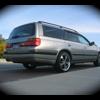
picked the car up last night. the install looks very tidy as expected.

i asked marty to leave the doors without sound deadening so i will have a weekend project to complete. hopefully i'll get it done tomorrow. i have the prepsol, the dynamat extreme and two diffusers. this will be the second car that i have done so hopefully everything goes smoothly.

then there was sound deadening (and more mid-bass).

i used dynamat extreme and diffuser (thanks FHRX for supplying).

i'm sure marty won't be sweating the loss of his livelihood any time soon. however, it is done.

this is not too difficult but requires patience and small flat screwdriver, a phillips head screwdriver, a 10mm spanner/socket, a stanley knife, prepsol some clean rags and it will pay to have some panel clips handy prior to starting in case some snap off removing the door trim.

there are only 4 screws holding right door trim on. two on the bottom, one in the middle towards the left side and one in the door recess/handle. all you need to do is gently lift up against the panel clips and it will virtually lift of the door handle surround will pop off in your hand. there are about three electrical plugs to disconnect (one of these was a tight little @#$%@!!). the left door is much the same except there is a 10mm bolt under the door handle which will become apparent when you lift the handle surround off. (once the three other screws have been undone if you lift the panel gently the cover may pop off in a similar manner to the other side. post-5777-1148805335.jpgpost-5777-1148805400.jpg

next remove the plastic. post-5777-1148805464.jpg

use your clean rags and prepsol to clean the door of grease wax dirt etc. clean inside the door skin as well.

make sure you inhale deeply and get that warm fuzzy high that solvents can give you. (of course protecting your hands and lungs is sensible). hopefully your door will look all sorta sexy like these after photos. post-5777-1148805761.jpg

next apply the diffuser behind the speaker with locktite or superglue. naturally there is a reinforcing bar in the door right where i wanted to put the diffuser so i installed it immediately above this bar.

next apply dynamat trying to cover all exposed metal surfaces. taking care not to apply it over the rails for the door locking mechanisms. these motors can burn out pretty easily if restricted in any way. any offcuts can be applied to any uncovered surface. i had to cut some strips to install onto the door skin. alternatively you could use sound deadening paint.

my doors ended up looking like this after. post-5777-1148806324.jpg

now replace any panel clips into the door trim and replace the door trim by reversing the order of installation. hopefully the doors will sound more solid. dynamat extreme 2kg/m is about half the weight of serenity max 4kg/ and it is much easier to work with as it is more pliable. i don't know which has better deadening properties.

the car sounds even better with lots more mid-bass. marty was staging the system late on friday night (for what must have been 1-1.5hrs) without the deadening installed which would have required enormous patience to get it sounding decent before we picked it up.

massive thanks to marty and the team at FHRXStudios.

ps. my finger have slashes in them from the dynamat when i was smoothing it down....now you shouldn't need stitches but my hands look like i had a hand holding date with freddy krueger. beer helps.

Edited by wolverine

2603_Sound_dBate_Door_Kit_English.pdf

some tech items from dynamat.

the drop of about 3db alone is worth considering but it is providing a more solid base for the action of the speakers. presumably lower frequencies will be most improved but i imagine other frequencies benefit. i'm very far from an expert but i know it sounds better.

and one from a corvette that shows the frequency changes.

2657_2000_Chevy_Corvette.pdf

Edited by wolverine

Create an account or sign in to comment

You need to be a member in order to leave a comment

Create an account

Sign up for a new account in our community. It's easy!

Register a new account

Sign in

Already have an account? Sign in here.

Sign In Now


  • Similar Content

  • Latest Posts

    • For once a good news  It needed to be adjusted by that one nut and it is ok  At least something was easy But thank you very much for help. But a small issue is now(gearbox) that when the car is stationary you can hear "clinking" from gearbox so some of the bearing is 100% not that happy... It goes away once you push clutch so it is 100% gearbox. Just if you know...what that bearing could be? It sounding like "spun bearing" but it is louder.
    • Yeah, that's fine**. But the numbers you came up with are just wrong. Try it for yourself. Put in any voltage from the possible range and see what result you get. You get nonsense. ** When I say "fine", I mean, it's still shit. The very simple linear formula (slope & intercept) is shit for a sensor with a non-linear response. This is the curve, from your data above. Look at the CURVE! It's only really linear between about 30 and 90 °C. And if you used only that range to define a curve, it would be great. But you would go more and more wrong as you went to higher temps. And that is why the slope & intercept found when you use 50 and 150 as the end points is so bad halfway between those points. The real curve is a long way below the linear curve which just zips straight between the end points, like this one. You could probably use the same slope and a lower intercept, to move that straight line down, and spread the error out. But you would 5-10°C off in a lot of places. You'd need to say what temperature range you really wanted to be most right - say, 100 to 130, and plop the line closest to teh real curve in that region, which would make it quite wrong down at the lower temperatures. Let me just say that HPTuners are not being realistic in only allowing for a simple linear curve. 
    • I feel I should re-iterate. The above picture is the only option available in the software and the blurb from HP Tuners I quoted earlier is the only way to add data to it and that's the description they offer as to how to figure it out. The only fields available is the blank box after (Input/ ) and the box right before = Output. Those are the only numbers that can be entered.
    • No, your formula is arse backwards. Mine is totally different to yours, and is the one I said was bang on at 50 and 150. I'll put your data into Excel (actually it already is, chart it and fit a linear fit to it, aiming to make it evenly wrong across the whole span. But not now. Other things to do first.
    • God damnit. The only option I actually have in the software is the one that is screenshotted. I am glad that I at least got it right... for those two points. Would it actually change anything if I chose/used 80C and 120C as the two points instead? My brain wants to imagine the formula put into HPtuners would be the same equation, otherwise none of this makes sense to me, unless: 1) The formula you put into VCM Scanner/HPTuners is always linear 2) The two points/input pairs are only arbitrary to choose (as the documentation implies) IF the actual scaling of the sensor is linear. then 3) If the scaling is not linear, the two points you choose matter a great deal, because the formula will draw a line between those two points only.
×
×
  • Create New...