Jump to content
SAU Community

Recommended Posts

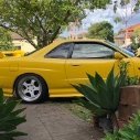
For sale: 1988 Nissan Cefiro

Asking Price: $15000

Killometer's: dash shows 55000, is most likely more

Manual or Automatic transmission: Manual

Engine Type: RB20DET silvertop out of R32

Modifications: SEE BELOW

Complianced: 15 y/old import

Road Worth Certificate: On request

Registration: Yes

Crash History: few marks around the body, is being cleaned up as you read :O

Other Comment's about the vehicle: SEE BELOW

Location : HORSHAM VIC (3 hrs north of Melbourne)(4.5 hrs east of Adelaide)

Contact detail's : Mellisa White / Phil Hobbs (03) 53824365 or 0400953788 ([email protected])

Engine

Silvertop RB20DET, blows no smoke, was installed after old original motor starting making funny noises

Blitz POD

FMIC, painted black for stealth

3 Core alluminium radiator

oil catch can

new plugs

fresh oil

boosted to 1bar

spats strut bar

3 inch turbo back exhaust

Interior

East Bear fixed bucket seat

Side mount seat rail

standard passenger seat

grey velour backseats

Nardi Steering wheel/boss kit

Trust gearknob

Omori Boost/Water temp/Oil pressure guages

7 Point rollcage

Laurel cluster (white lights, not green like all cefiro ones :) )

Profec B boost controller

Pivot Turbo timer

Exterior

Flared front and rear guards

Rare S1 Flat front lights

S2 rear tailights

now using standard bumpers (stealth look)

twin pipe exhaust tips

Buddy Club P1 bronze

17x8 +30

17x9 +19

Suspension

Full 5 stud conversion using S14 brakes/hubs AND longer control arms

Near new Capital-D coilovers

Caster rods

extended lock

Cusco rear camber arms

Rear toe arms

Cusco front/rear swaybars

NISMO 2-way LSD

Other Comments:

Have only just got the car back on the road recently after being in my dads shed for 12 months while i slowly added parts and performed engine swap. the rear guards have a little paint chipping where the guards have been flared. Paint is being applied to the std front + rear bumpers before sale, as well as the guards being cleaned up/painted. Diff is very tight and car handles like its on rails. have never been pulled up by the police in this car, and its built that way.

Perfect car for someone wanting to get into drifting or just want something for a cool daily. am willing to do swaps for fresh SR20 S13s or a nice falcon/commodore UTE (need tow car/daily).

PICS WILL BE UP TOMORROW WHEN I CAN TAKE SOME :banana:

Cheers

Phil Hobbs

Link to comment
https://www.sau.com.au/forums/topic/173752-cefiro-setup-for-funsliding-15k-neg/
Share on other sites

  • 2 weeks later...

Create an account or sign in to comment

You need to be a member in order to leave a comment

Create an account

Sign up for a new account in our community. It's easy!

Register a new account

Sign in

Already have an account? Sign in here.

Sign In Now


  • Similar Content

  • Latest Posts

    • For once a good news  It needed to be adjusted by that one nut and it is ok  At least something was easy But thank you very much for help. But a small issue is now(gearbox) that when the car is stationary you can hear "clinking" from gearbox so some of the bearing is 100% not that happy... It goes away once you push clutch so it is 100% gearbox. Just if you know...what that bearing could be? It sounding like "spun bearing" but it is louder.
    • Yeah, that's fine**. But the numbers you came up with are just wrong. Try it for yourself. Put in any voltage from the possible range and see what result you get. You get nonsense. ** When I say "fine", I mean, it's still shit. The very simple linear formula (slope & intercept) is shit for a sensor with a non-linear response. This is the curve, from your data above. Look at the CURVE! It's only really linear between about 30 and 90 °C. And if you used only that range to define a curve, it would be great. But you would go more and more wrong as you went to higher temps. And that is why the slope & intercept found when you use 50 and 150 as the end points is so bad halfway between those points. The real curve is a long way below the linear curve which just zips straight between the end points, like this one. You could probably use the same slope and a lower intercept, to move that straight line down, and spread the error out. But you would 5-10°C off in a lot of places. You'd need to say what temperature range you really wanted to be most right - say, 100 to 130, and plop the line closest to teh real curve in that region, which would make it quite wrong down at the lower temperatures. Let me just say that HPTuners are not being realistic in only allowing for a simple linear curve. 
    • I feel I should re-iterate. The above picture is the only option available in the software and the blurb from HP Tuners I quoted earlier is the only way to add data to it and that's the description they offer as to how to figure it out. The only fields available is the blank box after (Input/ ) and the box right before = Output. Those are the only numbers that can be entered.
    • No, your formula is arse backwards. Mine is totally different to yours, and is the one I said was bang on at 50 and 150. I'll put your data into Excel (actually it already is, chart it and fit a linear fit to it, aiming to make it evenly wrong across the whole span. But not now. Other things to do first.
    • God damnit. The only option I actually have in the software is the one that is screenshotted. I am glad that I at least got it right... for those two points. Would it actually change anything if I chose/used 80C and 120C as the two points instead? My brain wants to imagine the formula put into HPtuners would be the same equation, otherwise none of this makes sense to me, unless: 1) The formula you put into VCM Scanner/HPTuners is always linear 2) The two points/input pairs are only arbitrary to choose (as the documentation implies) IF the actual scaling of the sensor is linear. then 3) If the scaling is not linear, the two points you choose matter a great deal, because the formula will draw a line between those two points only.
×
×
  • Create New...