Jump to content
SAU Community

Recommended Posts

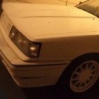
Hi all im new to Sau and very new to any turbo cars i have got my fathers 1995 nissan skyline as he has passed away January last year and as it was in the hands of the solicitors i have just got it a month ago but i havnt done much with it as my other toy a 1967 chev impala i have been putting a new engine into .

11377390_839137746169109_523314533395496

11351186_839138656169018_153749303800583

11108368_839137932835757_897204269907570

1455179_849439601805590_1498984525591091

11377390_839137746169109_523314533395496

the car got left out in the sun for 16 months and the clear on the roof has faded and my father broke the front bumper but i have fixed it up and my father had to have a auto because one of his leg got run over about 5 years ago so he couldnt drive a manual any more

This is my chev

539595_436305273119027_261824279_n.jpg

Link to comment
https://www.sau.com.au/forums/topic/458101-new-to-sau/
Share on other sites

i just wondering what that knob is behind the windscrean wipers

11329985_839138569502360_492092592835757

Also i headed the sydney last week end and went out to a skyline wreckers out at weatherill park and got some rims and i put them on the car today

11737933_873985329343946_708619538956006

11701030_873985836010562_358872565909879

this is how the front bumper was

11017784_852167701532780_273024966118428

and now how it looks i have never fibreglass before

11351335_852167668199450_876295737675892

Link to comment
https://www.sau.com.au/forums/topic/458101-new-to-sau/#findComment-7565279
Share on other sites

mate i found the paper work that come with the car when my dad bought it its got 1995 GTST r33 skyline to4 82r turbo hi mount, external waste gate, plazmaman plenum, gready computer ecu ,stage 3 shift kit gearbox 3000 rpm stall converter ,front mount intercooler , auto trans cooler , 600hp fuel pump , 306 hp at rear wheels at 10 psi boost 3 inch stainless exhaust all gtr body kit

Link to comment
https://www.sau.com.au/forums/topic/458101-new-to-sau/#findComment-7565959
Share on other sites

Create an account or sign in to comment

You need to be a member in order to leave a comment

Create an account

Sign up for a new account in our community. It's easy!

Register a new account

Sign in

Already have an account? Sign in here.

Sign In Now


  • Similar Content

  • Latest Posts

    • For once a good news  It needed to be adjusted by that one nut and it is ok  At least something was easy But thank you very much for help. But a small issue is now(gearbox) that when the car is stationary you can hear "clinking" from gearbox so some of the bearing is 100% not that happy... It goes away once you push clutch so it is 100% gearbox. Just if you know...what that bearing could be? It sounding like "spun bearing" but it is louder.
    • Yeah, that's fine**. But the numbers you came up with are just wrong. Try it for yourself. Put in any voltage from the possible range and see what result you get. You get nonsense. ** When I say "fine", I mean, it's still shit. The very simple linear formula (slope & intercept) is shit for a sensor with a non-linear response. This is the curve, from your data above. Look at the CURVE! It's only really linear between about 30 and 90 °C. And if you used only that range to define a curve, it would be great. But you would go more and more wrong as you went to higher temps. And that is why the slope & intercept found when you use 50 and 150 as the end points is so bad halfway between those points. The real curve is a long way below the linear curve which just zips straight between the end points, like this one. You could probably use the same slope and a lower intercept, to move that straight line down, and spread the error out. But you would 5-10°C off in a lot of places. You'd need to say what temperature range you really wanted to be most right - say, 100 to 130, and plop the line closest to teh real curve in that region, which would make it quite wrong down at the lower temperatures. Let me just say that HPTuners are not being realistic in only allowing for a simple linear curve. 
    • I feel I should re-iterate. The above picture is the only option available in the software and the blurb from HP Tuners I quoted earlier is the only way to add data to it and that's the description they offer as to how to figure it out. The only fields available is the blank box after (Input/ ) and the box right before = Output. Those are the only numbers that can be entered.
    • No, your formula is arse backwards. Mine is totally different to yours, and is the one I said was bang on at 50 and 150. I'll put your data into Excel (actually it already is, chart it and fit a linear fit to it, aiming to make it evenly wrong across the whole span. But not now. Other things to do first.
    • God damnit. The only option I actually have in the software is the one that is screenshotted. I am glad that I at least got it right... for those two points. Would it actually change anything if I chose/used 80C and 120C as the two points instead? My brain wants to imagine the formula put into HPtuners would be the same equation, otherwise none of this makes sense to me, unless: 1) The formula you put into VCM Scanner/HPTuners is always linear 2) The two points/input pairs are only arbitrary to choose (as the documentation implies) IF the actual scaling of the sensor is linear. then 3) If the scaling is not linear, the two points you choose matter a great deal, because the formula will draw a line between those two points only.
×
×
  • Create New...