
Announcements
-
Similar Content
-
-
Latest Posts
-
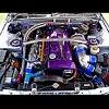
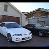
 A few small updates since the previous post and lessons. I decided to do a little interior light upgrade on the 110. I quite like the iilumo items, even if they're a bit of a premium over other brands. You'll also note the Stedi Fogs, that will go into the S15 fog lights as I needed to match the bulbs since I got the new ones earlier. I hope they fit as the body is quite a bit longer than your normal bulb. Annoyingly, I managed to trip the fuse, which normally wouldn't be an issue until I located the fuse. I can't say I've ever come across this. I had lucked out that someone nearby had a spare, but oddly enough Toyota dealerships seem to keep this in stock. I ordered some to keep in my stash and as luck would have it, someone else nearby tripped the same fuse so I passed on the favour. I also did a little service on the 110 ahead of some additional work coming up. It's been annoying that Goleby's stopped carrying this particular HKS filter for the 110, so now I need to keep them on order from Japan. I also took the opportunity to install a bash plate and number plate riser. The plate riser is such a cheap but nice fix to help really tidy up the car. I'm tempted to now also replace my headlights, on this car. Both items were from Project Aero. I also needed to replace the rear tyres on the 110, and after trying to get it aligned learnt that I need to replace some bushes in the front end, so that's next. Closing out this update with a nicer picture as always!
 -

-

-
 Appreciate the correction on the "ground", that will make a huge difference to looking at this. That makes complete sense about AF70/AF71 which is what I had come down to being the issue, one of these. I'll have another look in the ignition wiring when I get a chance next week. I'll also make up a jumper wire for running that AF73 test. ECU is fine, relay itself is fine, pump harness is fine and the pump itself is fine. I am going to upgrade the Walbro 255 anyway with a DW300 I have since I need to replace the fuel sender and I'm going to upgrade the FPR with my chasebays kit ready for new plenum/injectors/dbw, but I'll get this working first. That's why this is so frustrating.
 -

-


Recommended Posts
Create an account or sign in to comment
You need to be a member in order to leave a comment
Create an account
Sign up for a new account in our community. It's easy!
Register a new accountSign in
Already have an account? Sign in here.
Sign In Now