


BH_SLO32
-
Posts
500 -
Joined
-
Last visited
-
Feedback
100%
Content Type
Profiles
Forums
Events
Gallery
Media Demo
Store
Everything posted by BH_SLO32
-
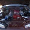
There should be a brown plug for the AAC (idle speed control). The purple plug is for the FICD solenoid. Basically it increases the idle when the AC is switched on. The dark blue plug is for the air regulator which operates independent of the ECU and is used to increase the idle when the engine is cold. The air regulator closes once the engine gets warm. If the AAC is not connected there must be another means of idle control (presumably you have an aftermarket ECU).
-
Is it an R33 RB26 loom you are using? Do you have a series 1 or 2 R33?
-
Rb20 Swapped S13 Will Not Run Right, Help!
BH_SLO32 replied to singlecamcammed240's topic in Engines & Forced Induction
The injector resistance is "high Impedance" hence normal. You clearly have an overfuelling problem given the AF ratio is maxed out. I would suggest you need a tune. It sounds like perhaps the ECU map is for some smaller (standard) injectors. -
Rb20 Swapped S13 Will Not Run Right, Help!
BH_SLO32 replied to singlecamcammed240's topic in Engines & Forced Induction
To check the impedance simply unplug an injector and using a multimeter and selecting resistance, simply place each lead on one of the injector terminals. Low impedance injectors will have a resistance of around 2ohms and high impedance will be around 12-14ohms. From what you have stated it sounds like a trip to the dyno is needed or a means to at least measure the AF ratios. -
My sister had to see Qld Transport to get a number of "defects" approved after an officer pulled her over in her R32Gtst. The front mount intercooler pipe came into the engine bay in the same spot as the GTR. As an engineer I simply prepared a letter for her essentially stating what has already been said. It will have neglible structural impact on the car. The fact that the GTRs have a hole in this location and on the passenger side there are more penetrations for the intercooler piping says it all really. When I had my RB30DET mod plate prepared, the approving facility included the front mount intercooler installation as part of the description for the modifications.
-
Pin 44 is the neutral signal. The ECU knows when the car is not in neutral.
-
A good indication if air is still in the line is the pedal sometimes won't return completely from the floor. There are 3 bleed points as you have already found. I use a one man bleeding system which comprises a small bottle and clear tube (can be purchased from SuperCheap, Repco etc). With some fluid in the bottle during the bleed process you can attach the clear tube to a bleed point and open it and pump the pedal as many times as required without the need to open and close the bleed during pedal movements as on the return stroke liquid from the bottle is sucked backwards rather than air being sucked back into the system. The clear tube allows you to see the air bubbles and once they stop you can close an move to the next point. I typically do all 3 points twice to ensure all air is removed. If the air is out of the system and you still can't engage the clutch you may need to adjust the pedal takeup point. The clutch master cylinder rod is attached to the pedal via a fork. The fork is threaded and its position on the rod can be adjusted by simply screwing it inwards or outwards and thereby adjusting the pedal position when the clutch engages. I have only just had to repair my fork as it stripped the thread and moved inwards (moved closer to the master cylinder) making the clutch engage when the pedal was just off the floor. I subsequently drilled the threaded portion out and welded a nut the back of it and screwed it outwards so now it wont be affected by my very heavy clutch and the clutch now engages when the pedal is halfway off the floor. Hope this helps.
-
Help Me Get My Tacho Reading Correctly.
BH_SLO32 replied to Simon-S14's topic in Engines & Forced Induction
You can use the digital speedo corrector from Jaycar. I built one sometime ago and tested on my R32. You need to adjust the frequency of the pulse and you cant do that with a resistor. With the 6 cylinder motors there are 3 pulses per revolution, with the 4 cylinders there are 2 pulses per revolution. This applies for 4 stroke engines. Consequently the silvia tacho will be out by the ratio of 3/2 (it will read 1.5x higher than actual engine revs). The resistor trick works with the R31 and VL as these factory tachos are looking for a pulsed feed however the RB20/25 ECU doesn't output a pulsed feed rather it simply earths a supplied power feed at the required frequency. The digital speedo corrector costs about $50 but requires assembly. It is not overly difficult to assemble. Recalibration of the factory tacho may be your cheaper option -
So your engine and loom is from a series 1 but is the donor a series 1 or 2? The power feed for the injectors is different and the series 2 doesn't have relay to switch the coils on like the series 1. The power feed to the switching side of the relay is missing in the series 2 loom.
-
Faulty Tacho Signal From Power Fc. Electrics Guru Needed..
BH_SLO32 replied to mark68's topic in General Maintenance
If you unplug the ECU and check pin 7 on the loom you should see around 5-10V with the IGN on. I am not sure on the wiring between the dash and the ECU but the ECU is fed power to pin 7. The ECU will then earth pin 7 to create a pulse (eg 5V-0V-5V-0V etc) at the required frequency. -
Faulty Tacho Signal From Power Fc. Electrics Guru Needed..
BH_SLO32 replied to mark68's topic in General Maintenance
There is a power feed to pin 7 (from the dash cluster presumably) and the ECU simply earths the signal to create the pulse. It is opposite to the old school feed from the coil (eg RB30). Cheers -
Car Shuts Off When Warm Whats Going On?
BH_SLO32 replied to Mr.Massive's topic in Engines & Forced Induction
Sounds like the fuel pump is switching off. I assume it is an R33 non-turbo with a turbo stagea motor added? -
I have had an intermittent problem with one of my cylinders firing and it is a problem in the actual coil pack wiring harness associated with the specific cylinder (#3 or 4 from memory). May pay to have a good look at the coil pack plug connection and if possible borrow someone elses coil pack loom to eliminate it from the equation.
-
I stumbled across a shootout of AFR gauges recently. Not a bad read. Wideband_O2_Shootout.pdf
-
Rb Wont Start With Haltech For Some Reason
BH_SLO32 replied to stricnynel0s's topic in Engines & Forced Induction
I had the power and earth wires switched when I wired the TPS up and consequently the TPS signal was reversed as in your case. Swapped them around without any issue. That said my car ran ok just had a nasty deadspot down low until I fixed it. It sounds like the timing the computer is seeing and the actual timing are quite different. Might explain why it will run initially with timing locked at 15 degs but then stall once the revs increase. -
Please Help! Rb25det Conversion Problems
BH_SLO32 replied to smokem31's topic in Engines & Forced Induction
You need the ECCS relay which plugs into the 4 pin plug you mentioned. This feeds power to the CAS, AFM and some pins on the ECU. Without this you won't be going anywhere! The fuel pump relay sounds like it is connected directly to earth (on the coil/trigger side). Consequently when the relay sees power it will switch on and stay on. The relay should be controlled via pin 18 on the ECU. It is the trigger/coil side of the replay that needs to be connected to pin 18. Assuming you use the same type of relay as the ECCS relay, the configuration should be 12V feed to pins 1 and 3 (ie connect the existing R31 fuel pump wire (white from memory)), pin 2 connected to pin 18 and pin 5 connected to earth. Pins 1 and 2 are the coil/trigger side and pins 3 and 5 are the switch side of th coil. Hope this helps. -
Rb25det Manifolds Onto Neo Engine
BH_SLO32 replied to ptharris's topic in Engines & Forced Induction
Thank you winstonusmc. The CAS on the R34 has a different locating piece to the R33 CAS so you cant just swap them over. Same goes for the VCT solenoid (refer photo in my first msg). The R34 CAS does however share the same connecting plug to the R33. -
Rb25det Manifolds Onto Neo Engine
BH_SLO32 replied to ptharris's topic in Engines & Forced Induction
A photo of the R33 intake gasket sitting in place on the Neo motor -
In front of the radiator and from memory it is supported off the bonnet latch support arm. It is a black rectangular unit.
-
Rb25det Manifolds Onto Neo Engine
BH_SLO32 replied to ptharris's topic in Engines & Forced Induction
I only recently went through this exercise with my fathers R33 series 1 engine which was replaced with a Neo engine. I bolted the intake manifold from the r33 onto the Neo but to do so I had to reuse the 2 studs a either end of the manifold as they are longer on the R33. I also used the thermostat housing from the R33 (larger diameter) but retained the R34 thermostat as it opens at about 82deg as opposed to 76degs on the R33. You will also need to use the coilpacks, VCT and CAS from the R34 as these are not interchangeable. I had to repin the CAS plug to suit the R34 CAS and wire in a mating plug for the R34 VCT. I used an R33 intake manifold gasket. I found the motor to be very smooth and great to drive. -
I have done more than a dozen Rb25 conversion looms for the R32 so can help if needed. Happy to provide a plugnplay loom too if you don't want the hassle of doing it yourself. Cheers Ben
-
I have some left over bits from an R33 GTST front cut. RB25 engine mounts GC $15 RB25 cross member GC $45 RB25 Power Steering Rack (rubber boots on ball joints are cracked and leaking) Overall GC $80 Or the lot for $100. Keen to part with these items so make an offer. Cheers Ben
-
I don't have the bottom timing cover but the top cover is still available. $40 for the lot.
-
Complete bottom end is sold.
-
Yes I have both. $80 each and in GC.
