Jump to content
SAU Community

Recommended Posts

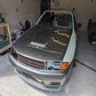
After many years a familly is finally reunited! The long lost RB26 now has a home.

Since its departure, the RB26 has come up against many set backs and life changing experiences. All this life experience has made it tougher and more powerful!

Its still settling back into its old surroundings with many previous connections to be re-established.

Deren

post-14108-1233470601_thumb.jpg

post-14108-1233470633_thumb.jpg

post-14108-1233470680_thumb.jpg

post-14108-1233470712_thumb.jpg

post-14108-1233470747_thumb.jpg

post-14108-1233470853_thumb.jpg

  • 3 weeks later...

So it turns out the 4-way filter remote mount i was planning to use is not going to be suitable. It has 2 inlets on one side and 2 outlets on the other, rather than having one of each kind on either side like i had hoped. So ive decided to go back to using the original filter mount which has one inlet and one outlet on the top. If i mount it sideways with the filter aimed forward i can access the outlet straight on and fit a 90 degree adapter to allow the inlet to plumb in from the core. Its going to save me a huge amount of money doing it this way.

More soon

Deren

post-14108-1235377300_thumb.jpg

post-14108-1235377575_thumb.jpg

post-14108-1235377638_thumb.jpg

A quick few pics of some parts trial fitted. Its a good thing i did as my oil filter remote mount had to be changed again. Ive found an excellent spot for it this time on the cross member below the engine mount. Its conveniantly located right next to the sump drain plug for easy oil changes from below.

Items trial fitted are:

Intercooler and plumbing including recirculation

Front reinforcement bar

Radiator, shroud and hoses

Oil cooler components

More soon,

Deren

post-14108-1235632409_thumb.jpg

post-14108-1235632487_thumb.jpg

post-14108-1235632562_thumb.jpg

Yours looks pretty neat just like mine before the build. One big step further has seen me spend a massive amount of cash over a period of nearly 4 years and counting! Ive setup the fuel pressure reg on the end of the rail as planned and it looks the goods. More pics soon.

Deren

Thanks ;) Planning on doing my resto after I've finished uni. Until then its my daily lol :rofl: Good luck with everything I'll be keeping an eye out for updates :) When its all finished we'll have to go for a cruise together :D

Sounds great, i'll look forward to that. Currently organising a few things which are holding me back from completing the front assembly. Gotta get off my ass and get all those gearbox bearing and seal numbers so i can order new ones too.

Most things in the pic are still just being trial fitted to check for compatibility and space etc. The fuel rail is one part which will receive some electro plating treatment to freshen it up before final fitting. I'll probably chrome it, either that or go with the original yellow cad plating that i will be getting redone on a few other bits.

Deren

post-14108-1236238524_thumb.jpg

post-14108-1236238646_thumb.jpg

post-14108-1236238946_thumb.jpg

Edited by Godzilla32

Hey everyone,

I've been busy organising bits and pieces over the last couple of weeks. Ive ordered all the necessary bearings today for my gearbox rebuild. Bought 3 remaining hoses from Nissan, 2 for coolant across the front of the timing cover and 1 for power steering fluid feed into the pump. Pieced together all the necessary Earls performance plumbing components. I wont tell you how much that cost to save you from heart failure :( It still needs to be fitted up properly and i have to make sure the over size oil cooler core will fit in the left inner guard.

I hope to have it running and driving but not completed by mid year and so far i look to be on track :cheers:

Im still yet to get those few engine bay parts re-plated at the electroplaters. I will try to arrange that in the next week or 2. There are a few other bits to refit in the front of the car but its slowly coming together now :)

Deren

  • 3 weeks later...

I have recently added stainless allen key bolts to various areas of the engine/bay. It has neatened up the appearance in some areas and added some more detail. I have ordered new glass mouldings to have the glass refitted with. Before it goes back in i will be getting the glass tinted too. Im currently getting some bits and pieces (including the fuel rail) plated in chrome and yellow chromate. All the detail helps :D I have completely trial fitted up the oil cooler and filter relocation setup now. With nearly everything ready for final fitting its looking good.

Deren

post-14108-1238231177_thumb.jpg

post-14108-1238231214_thumb.jpg

  • 2 weeks later...

I've started re-assembling the gearbox recently. Its coming together well so far. It was actually one of my most feared parts of the build, but i have been pleasantly suprised. Im replacing the ball bearings and im giving it all a check over. I hope to have it completed by the end of next week. From there i will strip the transfer case and give it a similar once over. Both the gearbox and transfer will be finished in the same dark silver i have used on the CAS, exhaust heat shields, etc.

Once they are completed i can refit the assembly and finally get ready for first fire and run-in on the dyno.

Deren

nice work deren!

i dont want to be a pain, but in that bolt pic, it looks like rust on the re-enforcement panel from the firewall to the strut tower. might just be the light and angle or dirt.

i like the look of the cup washers instead of just a bolt head -

IMG_0870.jpg

incase you havent seen or heard of them before

Its just the photo. Its actually a sealed join, just the light makes it look orange like rust. I assure you there is no dirt on the car, i have made sure of that :) Same goes for the rust. Its a very low milage car which was always garaged by its one previous owner. So it being overall in excellent condition has helped me in this rebuild. Those bolts look nice but im pretty happy with the ones ive chosen.

Deren

post-14108-1239182225_thumb.jpg

Its just the photo. Its actually a sealed join, just the light makes it look orange like rust. I assure you there is no dirt on the car, i have made sure of that :P Same goes for the rust. Its a very low milage car which was always garaged by its one previous owner. So it being overall in excellent condition has helped me in this rebuild. Those bolts look nice but im pretty happy with the ones ive chosen.

Deren

haha thats good news, i was freaken out for ya :D

Create an account or sign in to comment

You need to be a member in order to leave a comment

Create an account

Sign up for a new account in our community. It's easy!

Register a new account

Sign in

Already have an account? Sign in here.

Sign In Now


  • Similar Content

  • Latest Posts

    • For once a good news  It needed to be adjusted by that one nut and it is ok  At least something was easy But thank you very much for help. But a small issue is now(gearbox) that when the car is stationary you can hear "clinking" from gearbox so some of the bearing is 100% not that happy... It goes away once you push clutch so it is 100% gearbox. Just if you know...what that bearing could be? It sounding like "spun bearing" but it is louder.
    • Yeah, that's fine**. But the numbers you came up with are just wrong. Try it for yourself. Put in any voltage from the possible range and see what result you get. You get nonsense. ** When I say "fine", I mean, it's still shit. The very simple linear formula (slope & intercept) is shit for a sensor with a non-linear response. This is the curve, from your data above. Look at the CURVE! It's only really linear between about 30 and 90 °C. And if you used only that range to define a curve, it would be great. But you would go more and more wrong as you went to higher temps. And that is why the slope & intercept found when you use 50 and 150 as the end points is so bad halfway between those points. The real curve is a long way below the linear curve which just zips straight between the end points, like this one. You could probably use the same slope and a lower intercept, to move that straight line down, and spread the error out. But you would 5-10°C off in a lot of places. You'd need to say what temperature range you really wanted to be most right - say, 100 to 130, and plop the line closest to teh real curve in that region, which would make it quite wrong down at the lower temperatures. Let me just say that HPTuners are not being realistic in only allowing for a simple linear curve. 
    • I feel I should re-iterate. The above picture is the only option available in the software and the blurb from HP Tuners I quoted earlier is the only way to add data to it and that's the description they offer as to how to figure it out. The only fields available is the blank box after (Input/ ) and the box right before = Output. Those are the only numbers that can be entered.
    • No, your formula is arse backwards. Mine is totally different to yours, and is the one I said was bang on at 50 and 150. I'll put your data into Excel (actually it already is, chart it and fit a linear fit to it, aiming to make it evenly wrong across the whole span. But not now. Other things to do first.
    • God damnit. The only option I actually have in the software is the one that is screenshotted. I am glad that I at least got it right... for those two points. Would it actually change anything if I chose/used 80C and 120C as the two points instead? My brain wants to imagine the formula put into HPtuners would be the same equation, otherwise none of this makes sense to me, unless: 1) The formula you put into VCM Scanner/HPTuners is always linear 2) The two points/input pairs are only arbitrary to choose (as the documentation implies) IF the actual scaling of the sensor is linear. then 3) If the scaling is not linear, the two points you choose matter a great deal, because the formula will draw a line between those two points only.
×
×
  • Create New...