Jump to content
SAU Community

Recommended Posts

I have just received my turbotech boost controller and wondering how to fit it.

I know it goes between the wategate actuator and turbo but what does it look like and where is it?

Anyone have any pics of install?

I have a R33 gtst series 2.

Also when i fit it will the two stage boost solinoid still function or do i have to bypass it somehow?

CHEERS

dave

you have to bypass it run it. there should be a hose from you intercooler intake pipe to the solinoid run that to the boost controller and then run the boost controller back to the actuator..

do you have a boost gauge?

you'll want one..

  sinistagtst said:
Um a search or try diy section mite help you >_<

I have read the whole 64 pages of the boost controller thread and i still have no idea.I dont want to blow anything up

lol then it goes between the cooler pipe and the wastegate actuator, make sure its wound all the way down (check your manual), the stock boost controoler has 3 lines just take them off i think from memory one needs to be blocked up just use a screw or something. Then make sure you have a good boost gauge not the shit factory one and go for a drive it should be like 5psi etc then increase the boost little by little untill you get your required boost.... i hope i have helped

  sinistagtst said:
lol then it goes between the cooler pipe and the wastegate actuator, make sure its wound all the way down (check your manual), the stock boost controoler has 3 lines just take them off i think from memory one needs to be blocked up just use a screw or something. Then make sure you have a good boost gauge not the shit factory one and go for a drive it should be like 5psi etc then increase the boost little by little untill you get your required boost.... i hope i have helped

OK done.Now running a constant 9psi.Would this be a safe boost level for stock intercooler.I have a tube and fin kit waiting in the garage to be fitted.Then ill go 11psi.But then i get into the rich and retard bracket dont i.What are you running on your setup?

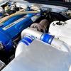
post-26632-1166237407.jpgthis is what you did right? its not very difficult, only two hoses.

you can take the stock solenoid out or leave it in the car, either way block all unused hoses by screwing a suitable screw into the end and maybe a zip tie over it. there is only one small hose you need to do this to though. if your having trouble maybe you forgot this bit lol.

  Quote
do u screw the bolt in for less boost or out? im still learnin haha

screw in for more boost, so when you first put it on have it screwed out so you dont overboost straight away, turn it bit by bit til you get to a good boost level.

PLEASE NOTE : this instruction is for turbotech design only, some other bleed valves may work differently.. if you have a different controller it may be the opposite. If so and you blow up your turbo dont come crying to me.

Create an account or sign in to comment

You need to be a member in order to leave a comment

Create an account

Sign up for a new account in our community. It's easy!

Register a new account

Sign in

Already have an account? Sign in here.

Sign In Now


  • Similar Content

  • Latest Posts

    • My guesstimate, with no real numbers to back it up, is it won't effect it greatly at all.its not a huge change in position, and I can't see the air flow changing from in turbulence that much based on distance, and what's in front of it. Johnny and Brad may have some more numbers to share from experience though.
    • Which solenoid? Why was it changed? Again, why was this done? ...well, these wear..but ultimately, why was it changed? Did you reset the idle voltage level after fitment? I'm just a tad confused ~ the flash code doesn't allude to these items being faulty, so in my mind the only reason to change these things, would be some drive-ability issue....and if that's the case, what was the problem? Those questions aside, check if the dropping resistor is OK ...should be 11~14 ohms (TCU doesn't throw a flash code for this) ~ also, these TCU designs have full time power (to keep fault code RAM alive), and I think that'll throw a logic code (as opposed to the 10 hardware codes), if that power is missing (or the ram has gone bad in the TCU, which you can check..but that's another story here perhaps).
    • Question for people who "know stuff" I am looking at doing the new intake like the one in the picture (the pictured is designed for the OEM TB and intake plenum), this design has the filter behind the front bar, but, the filter sits where the OEM duct heads into the front bar, and the standard aperture when the OEM ducting is removed allows the filter to pulled back out of the front bar into the engine bay for servicing, a simple blanking plate is used to seal the aperture behind the filter This will require a 45° silicone hose from the TB, like the alloy pipe that is currently there, to another 45° silicone hose to get a straight run to the aperture in the front bar Question: how will it effect the tune if I move the MAF about 100-150mm forward, the red is around where my MAF is currently, and the green would be where it would end up Like this This is the hole the filter goes through  Ends up like this LOL..Cheers    
    • Despite the level up question, actually I do know what that is....it is a pressure sender wire.  So check out around the oil filter for an oil pressure sender, or maybe fuel pressure near the filter or on the engine. Possibly but less likely coolant pressure sensor because they tend to be combined temp/pressure senders if you have one. Could also be brake pressure (in a brake line somewhere pre ABS) but maybe I'm the only one that has that on a skyline.
    • Pull codes via the self-diagnosis procedure. As far as I can tell this is just a sign of transmission issues but not a code unto itself.
×
×
  • Create New...