

Announcements
-
Similar Content
-
-
Latest Posts
-
 9" wheels are a little too wide for a RWD 32. They can fit. People have put R33 GTR wheels on 32s for years and years. But they are a very tight squeeze. This has been known for about 30 years. As I said - there is no difference between a 17 and an 18 in terms of what will fit. The rolling diameter needs to stay about the same as stock - not very much larger. If you increase that, you will start to have problems. If you increae rolling diamater at the same time as yo increase width, you will have problems earlier. as 9" wheels are pushing the boundaries already, you would need to be careful with tyre choice. I would put 8.5s on the front of mine, but would expect problems with 9s.
 -

By Dose Pipe Sutututu · Posted
post up screen shots of your injector tables -

By joshuaho96 · Posted
Diagnostic flow for a code 21 says check signal at the ECU pins, on a voltmeter of some kind it should read 0.1V at idle, 0.12V cranking, 0.15-0.25V at 2000 rpm. Check each coil such that +1, -3 is infinite or very high resistance, -3, +2 should do the same. (-1, +3), (+3, -2), (+1, -2), and (-1, +2) should all be somewhere between 0 ohms and high resistance. If you trace the path from the coil pin all the way back to the ECU in the diagram the resistance you measure at the coil vs connected to the harness should be pretty much the same. -

By feartherb26 · Posted
I have an elite 2500 running an adapter harness on an rb25de neo r34. I took the butterfly out and removed all that junk. But I also went Plus+t at the same time. The butterfly thing works in reverse to the boost solenoid on the Gtt if that makes sense -
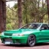 yeh they are 235/45/17 up front and 255/40/17 in the rears. I still didn't get my answer if i can fit a 18x9 up front. I want to get 4 of this and see if they will fit before committing as they didn't see an 18x8 as an option but there is a 18x9.5 also. Enkei RS05-RR 18x9 35mm ET 5x114.3 75.0 Bore Matte Gunmetal Wheel
-

1.thumb.png.36afd656b26d55f5d425fc76e21561f2.png)


Recommended Posts
Create an account or sign in to comment
You need to be a member in order to leave a comment
Create an account
Sign up for a new account in our community. It's easy!
Register a new accountSign in
Already have an account? Sign in here.
Sign In Now