Jump to content
SAU Community

Recommended Posts

Hey all,

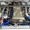
I found it very interesting and helpful following NTYSKY's rebuild so I thought I would post up my own. I have been saving and collecting these parts for years and finally its all coming together!

Motor is being build by Paul at Red R Racing.

Chassis is being built by myself and Louie at Exclusive Colours (XCM) - R33 40th ann. widebody, half cage, seem welded, etc

I realise some parts are overkill but my thoughts are better do it now.

Std virgin bore 05U block, prefer this over the rb30 3ltr.

HE modified sump RB26

Greddy Oil pump

N1 Water pump

86.5mm CP pistons and rings

Eagle ESP H beam rods with ARP rod bolts

Greddy cams 256 duration inlet 9.1 lift, 264 duration exhaust 9.1 lift

Greddy adjustable cam gears

Tomei timing belt

Tomei Bronze Valve guides RB26DETT In and Ex

Greddy Valve springs

Tomei Solid Valve Lifters RB26DETT Skyline GT-R R32

JUN Titanium Valve Retainers RB26DETT 0 Offset Type I

TRUST Greddy Strengthened Crank Cap Bolt Stud Set RB26

TRUST Greddy Strengthened Cam Cap Bolt Stud Set RB26

Trust Greddy Strengthened Cylinder Head Bolts RB26

HKS Valve Stem Seals RB26DETT Skyline GT-R R32 R33 R34

Power Enterprise Kevlar V belt, A/c, and alternator belts

Tomei Gasket Combination Set with 1.2mm metal head gasket

Tomei Oil Gallery Orifice - oil restrictor

CNC machined dash 8 head oil Drain

6boost low mount manifolds to suit GT25/30's

SARD 700cc Fuel Injectors RB26DETT Skyline

SARD Standard Type Adjustable Fuel Regulator #6an

Bosch 044 x 2 external, 040 internal, 1.5 ltr surge tank all braided teflon lines

Greddy 10.5 fuel rail twin entry

ATI balancer (once it f*ing arrives!!)

ACL std rod and main bearings calico coated

Mines Cam baffles

Standard intake manifold and throttle setup.

I will be running a Haltech E11v2 (thanks Scott & Ben) with all the goodies. Low mount GT2530's with greddy dumps and front pipe going into a Kakimoto 3.5 exhaust. Apexi intake pipe kit, JJR hard piping kit and a 600x300x76 cooling pro intercooler.

Car will be used for show and strip (eventually), All I need to sort out is the Gearbox, clutch and shafts.

Pics will be avaliable as soon as Paul is ready.

Cheers,

Link to comment
https://www.sau.com.au/forums/topic/228029-another-rb26-rebuild-thread/
Share on other sites

Crank has been checked and prepped and its in Sydney with rods and pistons getting balanced. Block has been stripped, acid bathed, hot tanked and grouted. Just waiting a little longer for the grout to properly cure before we bore and hone it. Will probably do the bore once the gear gets back from the balancers. The head has been ported and the guides are in. The port job is what we call a stage 2 job and is a little more involved than a simple clean up (stage 1). Its the same port job i did on my old 2530 engine, this port job was so good Jim at CRD didn't want it touched and asked me to source another head for my current engine. Will post up some pics of the progress as soon as i take the camera over and snap some.

Edited by DiRTgarage
Crank has been checked and prepped and its in Sydney with rods and pistons getting balanced. Block has been stripped, acid bathed, hot tanked and grouted. Just waiting a little longer for the grout to properly cure before we bore and hone it. Will probably do the bore once the gear gets back from the balancers. The head has been ported and the guides are in. The port job is what we call a stage 2 job and is a little more involved than a simple clean up (stage 1). Its the same port job i did on my old 2530 engine, this port job was so good Jim at CRD didn't want it touched and asked me to source another head for my current engine. Will post up some pics of the progress as soon as i take the camera over and snap some.

Do you have bench flow test information in-relation to your stage 1, stage 2 so forth and so on head porting options?

what brand bearings were used in the build? nismo, king etc etc

to what extent ( level ) did you fill the block up with grout to give it extra rigidity? what would be sufficient time for it to cure?

do you torque plate hone the block as part of a standard build?

Is there an option to xray the block prior to build to ensure no fractures exist?

Is the porting in the head free-hand with a dremel or is it CNC ported?

looking for a decent engine builder.

R

Heads are flow bench tested by my machine shop and we port the heads to suit turbo, cam selection, capacity and RPM range.

We use ACL race series bearings in most builds.

The level of grouting is something id prefer to keep to myself. But we have found even in a street application water temps are unaffected and in some applications is actually lower.

All builds are torque plate honed, we use a milled block as our dummy head as its nice and rigid and gives an even spread of torque over block deck.

We generally only chemical crack test the blocks, and if getting a little large in the bore 87mm^ Sonic testing is done to check cylinder wall thickness. X-raying can be done but blocks have to be freighted to Sydney.

Porting is done free hand with a die grinder

Hope this info helps.

Paul

Edited by DiRTgarage
Heads are flow bench tested by my machine shop and we port the heads to suit turbo, cam selection, capacity and RPM range.

We use ACL race series bearings in most builds.

The level of grouting is something id prefer to keep to myself. But we have found even in a street application water temps are unaffected and in some applications is actually lower.

All builds are torque plate honed, we use a milled block as our dummy head as its nice and rigid and gives an even spread of torque over block deck.

We generally only chemical crack test the blocks, and if getting a little large in the bore 87mm^ Sonic testing is done to check cylinder wall thickness. X-raying can be done but blocks have to be freighted to Sydney.

Porting is done free hand with a die grinder

Hope this info helps.

Paul

Thankyou very much for that info paul.

One question relating to your porting stages. If it was 272 / 272 10.25 lift cams, 2.8L HKS kit and either using 2860-r's ( 5 ) or going with a single top mount TZ-04 with a rpm range insight of 8500+/-rpm range

how would you then determine the stage of porting?

is you stages of porting from your machine shop determined by the amount material taken to increase the I.D of each port? or do you dyno with parts then remove head then port then re dyno...?

or is it a case of x brand turbos have Y max HP rating these cams have a power curve with z properties and the target max safe rpm is B amount therefore remove X amount from each port to do this which increases flow Y amount.....

sorry just trying to understand the porting stages.

Also can you / do you offer plasma coating as an option / stage for your engine rebuilds? ( cylinder bores )

R

Quick rundown of what each stage is

Stage one is mostly a clean up of whats already there, not a lot of material is removed and the port shape remains a very similar profile as a stock item. Suited to street applications with low mount turbo's with small lift and duration camshafts 7000-8000 rev limit

Stage two has the ports enlarged on both sides the port separators are modified slightly and the inlet is finished to aid in cylinder distribution and the exhaust is finished to minimise flow restriction. Suited to street cars that see the track often with larger flowing turbo's medium lift and duration camshafts 8000-9000 rev limit

Stage three has extensive enlargement and port shaping with full removal of the 'bump' in exhaust side and is perfectly matched to gaskets in port entry size. This is the extent the head on my race car has been ported as well as the head on other 'big' GTR's. Suited to full race applications and or dyno HP cars utilising very large turbocharger and high lift/duration camshafts 9000-10 000+ rev limit.

I have been intentionally a little vague about the exact modifications done as you can accept there is a lot of research done that im not willing to disclose on an open forum. Mostly this has been obtained through experience in real world conditions and not on a test bed/engine dyno (wish i had the time and money). Its done more along the lines of the xyzXY method you suggested.

Hope this info is of further assistance.

Edited by DiRTgarage

so ball park price for :

me send you engine , you build with my hardware, " stage 2 porting " prep block - line hone etc etc..... send back to me.

272 / 272 10.25 cams 2860-rs step 3 HKS stroker kit and associated uprated valve train hardware installed.....

cost ?

so ball park price for :

me send you engine , you build with my hardware, " stage 2 porting " prep block - line hone etc etc..... send back to me.

272 / 272 10.25 cams 2860-rs step 3 HKS stroker kit and associated uprated valve train hardware installed.....

cost ?

You have PM

sent...

forgot to answer the plasma coating question...

we only do it on our VQ38DETT rebuilds...lol

bloody good idea though...would save a lot of rebores...especially N1 blocks. Might look into that...cheers

Edited by DiRTgarage

No drama's Paul, the more info avaliable to the forum the better. :)

Dave, thanks mate should be awesome once its done.. just dont have much time to do the work!

Simon, I know mate.. chasing them up every morning lol, they will be sick of me by the end of it. lol

Create an account or sign in to comment

You need to be a member in order to leave a comment

Create an account

Sign up for a new account in our community. It's easy!

Register a new account

Sign in

Already have an account? Sign in here.

Sign In Now


  • Similar Content

  • Latest Posts

    • Getting the setup right, is likely to cost multiples of the purchase price of the vehicle.
    • So it's a ginormous undertaking that will be a massive headache but will be sorta cool if pulled off right. And also expensive. I'm sure it'll be as expensive as buying the car itself. I don't think you could just do this build without upgrading other things to take the extra power. Probably lots of custom stuff as well. All this assuming the person has mechanical knowledge. I'm stupid enough to try it but smart enough to realize there's gonna be mistakes even with an experienced mechanic. I'm a young bloke on minimum wage that gets dopamine from air being moved around and got his knowledge from a Donut video on how engines work.]   Thanks for the response though super informative!
    • Yes, it is entirely possible to twincharge a Skyline. It is not....without problems though. There was a guy did it to an SOHC RB30 (and I think maybe it became or already was a 25/30) in a VL Commode. It was a monster. The idea is that you can run both compressors at relatively low pressure ratios, yet still end up with a quite large total pressure ratio because they multiply, not add, boost levels. So, if the blower is spun to give a 1.4:1 PR (ie, it would make ~40 kPa of boost on its own) and the turbo is set up to give a 1.4:1 PR also, then you don't get 40+40 = 80 kPa of boost, you get 1.4*1.4, which is pretty close to 100 kPa of boost. It's free real estate! This only gets better as the PRs increase. If both are set up to yield about 1.7 PR, which is only about 70 kPa or 10ish psi of boost each, you actually end up with about 1.9 bar of boost! So, inevitably it was a bit of a monster. The blower is set up as the 2nd compressor, closest to the motor, because it is a positive displacement unit, so to get the benefit of putting it in series with another compressor, it has to go second. If you put it first, it has to be bigger, because it will be breathing air at atmospheric pressure. The turbo's compressor ends up needing to be a lot larger than you'd expect, and optimised to be efficient at large mass flows and low PRs. The turbo's exhaust side needs to be quite relaxed, because it's not trying to provide the power to produce all the boost, and it has to handle ALL the exhaust flow. I think you need a much bigger wastegate than you might expect. Certainly bigger than for an engine just making the same power level turbo only. The blower effectively multiplies the base engine size. So if you put a 1.7 PR blower on a 2.5L Skyline, it's like turboing a 4.2L engine. Easy to make massive power. Plus, because the engine is blown, the blower makes boost before the turbo can even think about making boost, so it's like having that 4.2L engine all the way from idle. Fattens the torque delivery up massively. But, there are downsides. The first is trying to work out how to size the turbo according to the above. The second is that you pretty much have to give up on aircon. There's not enough space to mount everything you need. You might be able to go elec power steering pump, hidden away somewhere. but it would still be a struggle to get both the AC and the blower on the same side of the engine. Then, you have to ponder whether you want to truly intercool the thing. Ideally you would put a cooler between the turbo and the blower, so as to drop the heat out of it and gain even more benefit from the blower's positive displacement nature. But that would really need to be a water to air core, because you're never going to find enough room to run 2 sets of boost pipes out to air to air cores in the front of the car. But you still need to aftercool after the blower, because both these compressors will add a lot of heat, and you wil have the same temperature (more or less) as if you produced all that boost with a single stage, and no one in their right mind would try to run a petrol engine on high boost without a cooler (unless not using petrol, which we shall ignore for the moment). I'm of the opinnion that 2x water to air cores in the bay and 2x HXs out the front is probably the only sensible way to avoid wasting a lot of room trying to fit in long runs of boost pipe. But the struggle to locate everything in the limited space available would still be a pretty bad optimisation problem. If it was an OEM, they'd throw 20 engineers at it for a year and let them test out 30 ideas before deciding on the best layout. And they'd have the freedom to develop bespoke castings and the like, for manifolds, housings, connecting pipes to/from compressors and cores. A single person in a garage can either have one shot at it and live with the result, or spend 5 years trying to get it right.
    • Good to know, thank you!
    • It's a place for non car talk. There's whoretown which is general shit talking. But also other threads coving all sorts of stuff(a lot still semi car related)
×
×
  • Create New...