
Announcements
-
Similar Content
-
-
Latest Posts
-

By R34_GT to Turbo · Posted
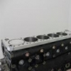
Looking to do a turbo conversion on my RB25DE Neo Does RB25DE Neo lower intake work with RB25DET Neo Upper intake manifold? I found an upper only intake manifold for sale but not sure if it will fit the bottom half stock intake manifold I have already? Thanks Also if your selling any parts relating to RB25DET Neo pls reply below or dm. -
-
By R34_GT to Turbo · Posted
Hi, wondering if the HKS bar and water reservoir still available? Thanks -
 What an awesome idea to fit the facelift Lamborghini Diablo headlights. They are a perfect fit!
 -

By hoodedreeper · Posted
An update regarding the registration with the DVLA I sent off the paperwork the day after I collected the car from the port, two weeks later it was all returned with a letter explaining they have rejected the application. This was because the cheque was £20 short for the road tax (I used a price list I found online). Nevermind it is what it is, it was sent back to them the following day with a new cheque. Fast forward another 2 weeks or so, I called them for an update to be told it had been rejected. Yesterday (16th September) I received the documents back along with another letter, this time it was because I didn't put an X in one box on the V750 (personalised number plate certificate), which declared that I had the rights to the personalised number plate. Why this wasn't mentioned in the first rejection letter, I don't know, but it could have saved this headache. The documents were sent back today, so fingers crossed third times a charm and it'll FINALLY be registered on the road just in time for the bad weather (woohoo!) To cheer myself up I lowered the front 25mm, was sick of seeing it sit like a monster truck. No idea how much clearance I'll have getting on and off the driveway, I'll worry about that when I can actually drive it
-


Recommended Posts
Create an account or sign in to comment
You need to be a member in order to leave a comment
Create an account
Sign up for a new account in our community. It's easy!
Register a new accountSign in
Already have an account? Sign in here.
Sign In Now