
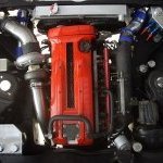
R34 Gt Intake Manifold

Announcements
-
Similar Content
-
-
Latest Posts
-

By GabsReDeal · Posted
After my last update, I went ahead with cleaning and restoring the entire fuel system. This included removing the tank and cleaning it with the Beyond Balistics solution, power washing it multiple times, drying it thoroughly, rinsing with IPA, drying again with heat gun and compressed air. Also, cleaning out the lines, fuel rail, and replacing the fuel pump with an OEM-style one. During the cleaning process, I replaced several hoses - including the breather hose on the fuel tank, which turned out to be the cause of the earlier fuel leak. This is what the old fuel filter looked like: Fuel tank before cleaning: Dirty Fuel Tank.mp4 Fuel tank after cleaning (some staining remains): Clean Fuel Tank.mp4 Both the OEM 270cc and new DeatschWerks 550cc injectors were cleaned professionally by a shop. Before reassembling everything, I tested the fuel flow by running the pump output into a container at the fuel filter location - flow looked good. I then fitted the new fuel filter and reassembled the rest of the system. Fuel Flow Test.mp4 Test 1 - 550cc injectors Ran the new fuel pump with its supplied diagonal strainer (different from OEM’s flat strainer) and my 550cc injectors using the same resized-injector map I had successfully used before. At first, it idled roughly and stalled when I applied throttle. Checked the spark plugs and found that they were fouled with carbon (likely from the earlier overly rich running when the injectors were clogged). After cleaning the plugs, the car started fine. However, it would only idle for 30–60 seconds before stalling, and while driving it would feel like a “fuel cut” after a few seconds - though it wouldn’t fully stall. Test 2 – Strainer swap Suspecting the diagonal strainer might not be reaching the tank bottom, I swapped it for the original flat strainer and filled the tank with ~45L of fuel. The issue persisted exactly the same. Test 3 – OEM injectors To eliminate tuning variables, I reinstalled the OEM 270cc injectors and reverted to the original map. Cleaned the spark plugs again just in-case. The stalling and “fuel cut” still remained. At this stage, I suspect an intermittent power or connection fault at the fuel pump hanger, caused during the cleaning process. This has led me to look into getting Frenchy’s fuel hanger and replacing the unit entirely. TL;DR: Cleaned and restored the fuel system (tank, lines, rail, pump). Tested 550cc injectors with the same resized-injector map as before, but the car stalls at idle and experiences what feels like “fuel cut” after a few seconds of driving. Swapped back to OEM injectors with original map to rule out tuning, but the issue persists. Now suspecting an intermittent power or connection fault at the fuel pump hanger, possibly cause by the cleaning process. -
 For race cars, this is one part where I find having the roll cage bar having gone through a hole in the floor better than the build it up on a ledge inside... The Merc I help on, the main hoop ends are marked on the car, and the jack is marked... Jack goes under a few inches and lifts one whole side of the car up... Removes that fight for long slim jacks for race car duties! My biggest issue for the daily drivers I work on, is my jacks don't go high enough. The jacks start out on a few blocks, jack it up, then start a second jack under it on more blocks, and then I can get an axle stand under it. My axle stands are presently in use, and are nearly fully extended. The car is sitting with barely more than a cm of clearance to get the wheel off the studs! Sarah's Kluger is the same, as it has an ungodly amount of droop available in the suspension and a distinct lack of good jacking points!
 -
-
 Sorry I meant that we are building the EH for a client.
 -
 LOL, when one "money pit" is never enough Noice, and excellent work mate
-


Recommended Posts
Create an account or sign in to comment
You need to be a member in order to leave a comment
Create an account
Sign up for a new account in our community. It's easy!
Register a new accountSign in
Already have an account? Sign in here.
Sign In Now