
Announcements
-
Similar Content
-
-
Latest Posts
-
 It does sound like a fuse considering the indicators work..I’ll triple check when I’m free and report back. thanks for the reply.
 -
 no, the car was a manual 5 speed from the factory and still is.
 -

By TurboTapin · Posted
While going through data logs late last week, I spotted a small issue with my WMI. My WMI starts to progressively inject at 11psi of boost. I'm using a 25psi cut in pressure switch on my WMI as an added safety and if the curve is linear, I should hit that 25psi on my WMI system around 13-14psi of boost. As per my data logs, my WMI pressure switch only activates around 19psi of boost. This is causing my non WMI 4D map to trim for WMI. I'm presuming this is caused by the mechanical switch response time, injection curve not being linear or both. I ordered a 2-10psi adjustable cut in pressure switch which should correct this. If this doesn't resolve it before my dyno appointment on Friday, I'll just remove the pressure switch temporarily and more than likely replace it with a pressure transmitter afterwards. BTW Speedtek has yet to refund me. -
 Yep PETG (Polyethylene terephthalate glycol), my 'go to' plastic, printed to precisely how long I wanted 🙂, about a finger length ha ha. I would usually grind up something but since I've got the printer I thought I might give it a try and it worked beautifully ^_^b So with regards to torque, there's a little bit of science behind the orientation of the print, fill density, fill pattern and number of external perimeters which can increase the strength dramatically, but you still need to work within the constraints of the material and the orientation of the model for sure. I certainly wouldn't be making a breaker bar out of plastic, but this little bugger is very strong for it's size that's for sure.
 -

By GoHashiriya · Posted
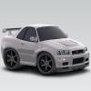
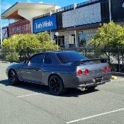
This is the part I was unprepared for. I mean, thinking about it now, the first day I collected my car from the importer someone posted a photo of it on the highway to an online JDM page which my friend then sent me. I drove straight to the office to pick up some things and was immediately swarmed by about ten college kids - "how much power" "why no wing" etc. The next couple times I went out I didn't really notice anything, there was a "why no wing" at a service area at some point. Then during the fourth time out driving at the Nurburgring I got the "do a drift" - the bastard cut it out in this clip. The title in itself is a red flag. As you may have guessed, I am not a fan of the attention. This leads me to wondering what to do with the car in the future; I'll see how this year goes and it may be garaged, which it mostly is already, or maybe even sent back to Japan to also be garaged and driven occasionally on visits. Fortunately my daily is as interesting as drying paint.
-


Recommended Posts
Create an account or sign in to comment
You need to be a member in order to leave a comment
Create an account
Sign up for a new account in our community. It's easy!
Register a new accountSign in
Already have an account? Sign in here.
Sign In Now