

Announcements
-
Similar Content
-
-
Latest Posts
-
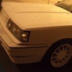
 So, before putting them in I need to understand the stock ride height. This is how I measured it: First, check the diameter of the wheel's centre cap, it was 52mm. Then put a piece of masking tape approximately across the centre and measure 27mm (half) from at least 3 sides to get a reasonable idea of the centre of the wheel cap. Mark that with a horizontal line as one measuring point. Then, directly above the wheel on the guard, put another piece of masking tape in approximately the centre. Use a string line to find out the point on the guard above the centre of the wheel cap and mark that. Then it is simple, just a tape measure to check the distance from centre of the wheel to the centre of the guard. Final results where LF: 381mm RF: 379mm LR: 401mm RR: 400mm Pretty even considering they are 120,000klm old factory springs, lets call that 380 front and 400 rear.
 -
So....knowing that I have a problem with power steering temps on track and another Wakefield day booked in next Friday, I've done the obvious thing They are very reasonably priced at $1650, considering they are a big monotube shock, double height adjustable (don't have to change pre-load to change ride height), one way adjustable damping and standard sized and customisable springs if you want something other than what comes with them. They come with 9kg/mm front and 4.5kg/mm front and I went with that as a starting point because I'll add adjustable sway bars too https://justjap.com/products/bc-racing-coilover-kit-ds-ds-infiniti-q50-v37-14-current#description Unfortunately they didn't come with rear strut tops so I've re-used the factory ones which was a bit of a pain. Also, the adjuster for the rear shock will be an absolute nightmare to get at, and while there are extensions in the kit I can't see any way you can actually attach or use them
-
I also had 2 bulbs blow at once, years ago in the stagea. made for a fun drive home. The issue was the voltage regulator had failed in the alternator and it was giving 15+ volts. Really, I was lucky all that was fried were the headlight bulbs. So, I'd suggest you check the voltage across your battery terminals with the car running and warmed up. Yes, you will need a multimeter to do so, sorry.
-
Good work to think to check that, and thanks for coming back to post up the outcome.
-
Given it happened suddenly, and when you come on boost, I'd check all your inlet - hose clamps in place and no split rubber or silicone hoses. Even the hard to get to ones near the intercooler. It's possible air that went past the air flow meter is being dumped out a big hole.
-


Recommended Posts
Create an account or sign in to comment
You need to be a member in order to leave a comment
Create an account
Sign up for a new account in our community. It's easy!
Register a new accountSign in
Already have an account? Sign in here.
Sign In Now