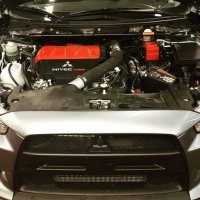
Knock sensor harness location/access?
Announcements
-
Similar Content
-
Latest Posts
-
So, I've had my V36 for about a month now and have already copped an "excessive exhaust noise" notification from QLD TMR, reported by someone in my local area. It's a twin as per the original, and can have a bit of a throaty note to it when idling cold 😄 and if I do get up it a bit, it can be noisy, but it did pass a roadworthy inspection before sale, so.... ... but in the interest of being a good neighbour, I do want to quieten it down a bit. Is anyone here running a quiet aftermarket cat-back on their V36 or 370Z? And the big, bold question: does an aftermarket cat-back really make much of a performance difference on these cars?
-
The wiring diagram for the R33 RB25 is freely available, and is essentially the same same as most other RBs (just with differences as to which pin # does which job). To get the ECU to power up, you just need to provide power to the ECCS relay, and have the other power feeds that come in from the top left of the wiring diagram (wrt the ECU) that give perma power to the fuel pump relay, the ECU itself, etc etc, all connected. When you put power on all these it will just come to life. It's pretty clear from the diagram what needs to happen. Just follow the lines from the 12V + supply stuff in the top left over towards the ECU. I've even posted snips of such diagrams (not for vanilla 25, I think for Neo and 26) to various threads here in the last few months, talking about what it takes to get the fuel pump and FPCM up and going. Search these up and they will help get you started on doing the same with the vanilla 25 diagram. Hell, for all I know, I've done the same with that one in years past and have forgotten.
-
Yep...so unless someone posts up the answer you will need to probe from the ECU connector to the dash plug with a multi meter in continuity mode to trace the wires. Note the ECU has multiple - and + (and across different key settings - Battery, IGN and Start) and most likely the power is fed from the connector(s) that is normally near the left hand headlight.
-
Thanks Duncan, I am actually just trying to get the Rb turning and running with the RB25DET S2 original loom itself I am just trying to get it going outside the body and not thinking about the S15 or trying to match anything to the S15 loom at all I am only trying to see if anyone has done this and what pin they found to be the ignition trigger and ECU+/- on the dash connector, that's about it. Thanks
-
By iain_ST44GA · Posted
Hi Guys, Does anyone know any aftermarket part numbers for a starter motor to suit the VQ25DET? I can find lots of alternative part number for the VQ35DE, which I assume would fit, but there is a lot of conflicting information out there. Thanks..
-


.thumb.jpg.1b7f9b555236b5ea56c3fed20c733de8.jpg)
Recommended Posts
Create an account or sign in to comment
You need to be a member in order to leave a comment
Create an account
Sign up for a new account in our community. It's easy!
Register a new accountSign in
Already have an account? Sign in here.
Sign In Now