
Announcements
-
Similar Content
-
-
Latest Posts
-
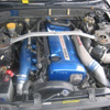
 Decided for the first time ever I would tow my car TO the track day on the same working theory as bringing tools and spares "if I have it I wont need it, but if I leave it behind i will 100% need it" all setup and ready to go out and try these A050 for the first time First session showed I needed to stiffen up the dampers a touch but still managed a few 1:21's without much effort. things were looking good. Came in a dropped the tyres down to 26/28 as they had gotten to 35/33C from 22C cold The first lap of session two I managed to drop into 1:20's. Then in the second lap into the second session. Coming into T3 and I suddenly lost brake pedal followed by some huge rear end vibrations and scraping sounds. Got it back into the pits after session ended and found this. in the attached video, all of the wobble is in the hub its self, wheel is mint, and bearing feels tight. lKXLqpd - Imgur.mp4 Deciding it was a bent spindle I tried to find bearing/hub assembly locally but was unsuccessful so it was loaded back onto the trailer i luckily brought it on to drag it back home
 -

-

By joshuaho96 · Posted
You have to continuously fill it to avoid dry running. Personally the transmissions I've serviced have never been bad enough to justify doing this because it is definitely a pretty complicated and somewhat risky procedure compared to simply draining the pan, measuring what came out, then refilling with the exact same amount. -
 So...I thought about that (muuuuuch easier!) but I wasn't confident running the pump dry by doing that....is it safe?
 -
By joshuaho96 · Posted
I did basically the same procedure on a ZF6HP but the reason to pull the valve body is to replace the seals between the valve body and the transmission which are notorious for leaking pressure with age causing poor shifting and burning out the clutches. If you just wanted to exchange all the fluid you should be able to undo one of the transmission cooler return lines to drain into a bucket while using the pressure filler to keep it topped off.
-


Recommended Posts
Create an account or sign in to comment
You need to be a member in order to leave a comment
Create an account
Sign up for a new account in our community. It's easy!
Register a new accountSign in
Already have an account? Sign in here.
Sign In Now