Jump to content
SAU Community

Recommended Posts

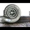
I just bought an 040 to replace my fuel pump and have some questions about the install.

I know you cut the bottom of the standard bracket and clamp the pump to the side of the existing bracket with rubber inbetween to stop vibration. What I need to know is:

do you need to use a filter with the 040 or is there a filter on the bottom of the pump underneath the mesh base?

will can the existing fuel line fit over the fitting on the 040 and then be clamped on or do I need a screw fitting of some type?

Can you get a pump assembly gasket from nissan? they said they only come in kits.

If someone would be kind enough to list a "what you need" list.

Also I spent 1/2 an hour digging thru "pump" bosch" 040" threads looking for a photo of one mounted on a bracket but couldn't find one and I was sure I had seen one here before.

thankyou!

sounds good. Did you need to use a new tank seal? and where do you get one.

also are the electrical contacts on the old pump the same? I just want to get everything I need before I pull the car apart.

You will need to find 2 nuts that fit over the 040 terminals

Then just need to solder on some connectors onto the standard wiring and secure them to the pump with the nuts

New tank seal is a good idea, Nissan should be able to source you one

Hi mate, good luck.

I had mine installed by the mechanics/tuners along with a lot of other gear at the same time, so I cant help much.

Two suggestions: a) I had them direct wire it to the battery feed, so it runs at ~13.8v and not 12v. b) I also made directions that the 040 pump MUST be installed as low in the tank as possible. That way I have no fuel issues, I can go down to near empty and be all ok.

Thanks Chris. I will buy the bits I need.

No Probs

Another thing I found helped, angle the return feed away from the pickup point, as with the higher volume pump, it causes cavitation in the fuel (air bubbles) due to much more fuel being pumped back than the stocker. You might have heard it on some cars with up-graded pumps, sound like the pump is sucking in air

I acutally trimmed my fuel return pipe and attached some fuel hose and angled it well away from the pickup point of the pump. The fuel returning is generally much warmer too.

Wiring it straight of the battery is also a good idea, you can do that later if you find the supply is not enough

I think Cubes did a DIY thingo about that

DO you need to wire directly from battery or will the 040 pump b ok off of the stock wiring. Will just not pump it's maximum pumping capcity when on stock wiring.

My guess with wiring off of the battery is that the ignition crontrolls the relay that switches the pump on throught the battery is that right?

Edited by Madtrang

It's a 12V pump, running it at 13.8 volts does not do anything except heat it up more. You need to cut the earth wire to the pump and direct earth it to the body in the boot somewhere. This removes the dropping resistor from the equation. The resistor is what drops pump speed when you come to idle.

It's a 12V pump, running it at 13.8 volts does not do anything except heat it up more. You need to cut the earth wire to the pump and direct earth it to the body in the boot somewhere. This removes the dropping resistor from the equation. The resistor is what drops pump speed when you come to idle.

Is that necessary. If your @ idle u dont need alot of fuel being pumped or are there other reasons why it's a good practise to ground it properly.

Create an account or sign in to comment

You need to be a member in order to leave a comment

Create an account

Sign up for a new account in our community. It's easy!

Register a new account

Sign in

Already have an account? Sign in here.

Sign In Now


  • Similar Content

  • Latest Posts

    • perhaps i should have mentioned, I plugged the unit in before i handed over to the electronics repair shop to see what damaged had been caused and the unit worked (ac controls, rear demister etc) bar the lights behind the lcd. i would assume that the diode was only to control lighting and didnt harm anything else i got the unit back from the electronics repair shop and all is well (to a point). The lights are back on and ac controls are working. im still paranoid as i beleive the repairer just put in any zener diode he could find and admitted asking chatgpt if its compatible   i do however have another issue... sometimes when i turn the ignition on, the climate control unit now goes through a diagnostics procedure which normally occurs when you disconnect and reconnect but this may be due to the below   to top everything off, and feel free to shoot me as im just about to do it myself anyway, while i was checking the newly repaired board by plugging in the climate control unit bare without the housing, i believe i may have shorted it on the headunit surround. Climate control unit still works but now the keyless entry doesnt work along with the dome light not turning on when you open the door. to add to this tricky situation, when you start the car and remove the key ( i have a turbo timer so car remains on) the keyless entry works. the dome light also works when you switch to the on position. fuses were checked and all ok ive deduced that the short somehow has messed with the smart entry control module as that is what controls the keyless entry and dome light on door opening   you guys wouldnt happen to have any experience with that topic lmao... im only laughing as its all i can do right now my self diagnosed adhd always gets me in a situation as i have no patience and want to get everything done in shortest amount of time as possible often ignoring crucial steps such as disconnecting battery when stuffing around with electronics or even placing a simple rag over the metallic headunit surround when placing a live pcb board on top of it   FML
    • Bit of a pity we don't have good images of the back/front of the PCB ~ that said, I found a YT vid of a teardown to replace dicky clock switches, and got enough of a glimpse to realize this PCB is the front-end to a connected to what I'll call PCBA, and as such this is all digital on this PCB..ergo, battery voltage probably doesn't make an appearance here ; that is, I'd expect them to do something on PCBA wrt power conditioning for the adjustment/display/switch PCB.... ....given what's transpired..ie; some permutation of 12vdc on a 5vdc with or without correct polarity...would explain why the zener said "no" and exploded. The transistor Q5 (M33) is likely to be a digital switching transistor...that is, package has builtin bias resistors to ensure it saturates as soon as base threshold voltage is reached (minimal rise/fall time)....and wrt the question 'what else could've fried?' ....well, I know there's an MCU on this board (display, I/O at a guess), and you hope they isolated it from this scenario...I got my crayons out, it looks a bit like this...   ...not a lot to see, or rather, everything you'd like to see disappears down a via to the other side...base drive for the transistor comes from somewhere else, what this transistor is switching is somewhere else...but the zener circuit is exclusive to all this ~ it's providing a set voltage (current limited by the 1K3 resistor R19)...and disappears somewhere else down the via I marked V out ; if the errant voltage 'jumped' the diode in the millisecond before it exploded, whatever that V out via feeds may have seen a spike... ....I'll just imagine that Q5 was switched off at the time, thus no damage should've been done....but whatever that zener feeds has to be checked... HTH
    • I think Fitmit had some, have a look on there (theyre Australian as well)
    • Hah, fair enough! But if you learn with this one you can drive any other OEM manual. No modern luxury features like auto rev-matching or hillstart assist to give you a false sense of confidence. And a heavy car with not that much torque so it stalls easily. 
×
×
  • Create New...