Jump to content
SAU Community

Recommended Posts

hey guys,

have been searching for some time so im ging for gold if someone could help me out :)

I bought this cheapy bloody kit for ebay

http://cgi.ebay.com.au/FMIC-TURBO-INTERCOO...1QQcmdZViewItem

Just need a pic of a bay so i can see the pipe that runs past the alternator and meets with the last pipe to the manifold, where it runs through. Do i need to take the whole bottom plastic engine shield off or just cut a hole. Which side does it run up?

Sorry if i sound a bit sketchy, have already had half a case of woody blues. Any pics would be greatly appreciated! cheers boys.. and girls.

really what i need is anyone who has installed an fmic on 33 series2 with a cooler that has outlet and inlet directing to opposite sides. i think i will need to cut a hole under the water bottle somewhere so i can get the pipe through and come out above the alternator.. . anyone???

you are correct! if you were qld i could lend you the hole saw as well.

post-17300-1172298834.jpg

EDIT I only have a 86mm hole saw with no arbour to drive it, stupid me never checked that ones I had, do fit it.

you are correct! if you were qld i could lend you the hole saw as well.

post-17300-1172298834.jpg

dude seriously you are a legend. i have just cut a hole there and it all marries up but im glad you posted that anyway. Mods might like to tech faq this one...

cheers :D

You don't actually attatch it to the solenoid, you by-pass the solenoid altogether.

Pretty sure the top pipe on the solenoid travels to a metal T-piece connected to a feed that goes from the intercooler piping down into the depths of the engine bay...well into the turbo/actuator.

The boost controller you have takes the place of that that T-piece.

Then block off the pipe that you removed that goes to the solenoid, never to be used again.

The boost controller will then be doing the job of the solenoid.(controlling the pressure feed from the I/C pipe to the wastegate-actuator)

Start with it screwed in, undo a few turns, drive....too low? undo a few more turns and repeat.

forget that, anyone got a pic or link to a pic for a hookup of a two piece manual boost controller.

bottom piece goes to actuator, what does the top pipe go to?? any pics pleae guys... life savers!!!

Connect one end of the boost controller to the nipple on the intercooler piping and the other to the wastegate actuator (attached to the turbo)

If you have one of the cheaper IC kits then you might not have a nipple on the cooler piping (usually closest as possible to the throttle body)....if you dont then purchase a $2 nipple and tap it into the piping making sure its a nice fit. Temporarily you can connect that end to the BOV vacuum hose(the one at the top) to drive yourself over to repco or whatever.

PM me if you still have trouble

Start with it screwed in, undo a few turns, drive....too low? undo a few more turns and repeat.

ummmm...isnt it then other way around. Undo (anti-clockwise) decreases boost...not increases

Connect one end of the boost controller to the nipple on the intercooler piping and the other to the wastegate actuator (attached to the turbo)

If you have one of the cheaper IC kits then you might not have a nipple on the cooler piping (usually closest as possible to the throttle body)....if you dont then purchase a $2 nipple and tap it into the piping making sure its a nice fit. Temporarily you can connect that end to the BOV vacuum hose(the one at the top) to drive yourself over to repco or whatever.

PM me if you still have trouble

sorry to bring this question up but im installing a FMIC myself and it doesnt have the nipple, were do you buy these from and how do you tap into the piping, is there welding involved or sumthin?

cheers

Confusing thread as you started on 1 topic and then edited the title to another....anyways...

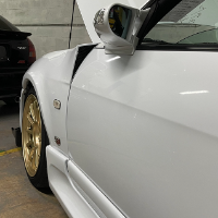
here's some pics from yours truly.

Don't take the hole i made as the exact spot though, measure it up yourself and be sure it's right 50 times before cutting.

Good luck.....

http://www.skylinesaustralia.com/forums/in...110032&st=0

Create an account or sign in to comment

You need to be a member in order to leave a comment

Create an account

Sign up for a new account in our community. It's easy!

Register a new account

Sign in

Already have an account? Sign in here.

Sign In Now


  • Similar Content

  • Latest Posts

    • Have a look at that (shitty) pic I posted. You can see AN -4 braided line coming to a -4 to 1/8 BSPT adapter, into a 1/8 BSPT T piece. The Haltech pressure sender is screwed into the long arm of the sender and factory sender (pre your pic) into the T side. You can also see the cable tie holding the whole contraption in place. Is it better than mounting the sender direct to your engine fitting......yes because it removes that vibration as the engine revs out 50 times every lap and that factory sender is pretty big. Is it necessary for you......well I've got no idea, I just don't like something important failing twice so over-engineer it to the moon!
    • Yup. You can get creative and make a sort of "bracket" with cable ties. Put 2 around the sender with a third passing underneath them strapped down against the sender. Then that third one is able to be passed through some hole at right angles to the orientation of the sender. Or some variation on the theme. Yes.... ummm, with caveats? I mean, the sender is BSP and you would likely have AN stuff on the hose, so yes, there would be the adapter you mention. But the block end will either be 1/8 NPT if that thread is still OK in there, or you can drill and tap it out to 1/4 BSP or NPT and use appropriate adapter there. As it stands, your mention of 1/8 BSPT male seems... wrong for the 1/8 NPT female it has to go into. The hose will be better, because even with the bush, the mass of the sender will be "hanging" off a hard threaded connection and will add some stress/strain to that. It might fail in the future. The hose eliminates almost all such risk - but adds in several more threaded connections to leak from! It really should be tapered, but it looks very long in that photo with no taper visible. If you have it in hand you should be able to see if it tapered or not. There technically is no possibility of a mechanical seal with a parallel male in a parallel female, so it is hard to believe that it is parallel male, but weirder things have happened. Maybe it's meant to seat on some surface when screwed in on the original installation? Anyway, at that thread size, parallel in parallel, with tape and goop, will seal just fine.
    • How do you propose I cable tie this: To something securely? Is it really just a case of finding a couple of holes and ziptying it there so it never goes flying or starts dangling around, more or less? Then run a 1/8 BSP Female to [hose adapter of choice?/AN?] and then the opposing fitting at the bush-into-oil-block end? being the hose-into-realistically likely a 1/8 BSPT male) Is this going to provide any real benefit over using a stainless/steel 1/4 to 1/8 BSPT reducing bush? I am making the assumption the OEM sender is BSPT not BSPP/BSP
    • I fashioned a ramp out of a couple of pieces of 140x35 lumber, to get the bumper up slightly, and then one of these is what I use
    • I wouldn't worry about dissimilar metal corrosion, should you just buy/make a steel replacement. There will be thread tape and sealant compound between the metals. The few little spots where they touch each other will be deep inside the joint, unable to get wet. And the alloy block is much much larger than a small steel fitting, so there is plenty of "sacrificial" capacity there. Any bush you put in there will be dissimilar anyway. Either steel or brass. Maybe stainless. All of them are different to the other parts in the chain. But what I said above still applies.
×
×
  • Create New...