Jump to content
SAU Community

Recommended Posts

Hi all,

this is my first post in this great forum, but it's not my first visit :D

i've searched for tech information about RB26 but i found many topics about conversion between RBs and so on. anyway, i'm building my RB26 for my GTR R32, and i'm looking to make 600 awhp.

now, i've ordered a set of CP pistons (87.0 mm), Eagle rods (H beam, with ARP bolts), ARP Bolts and Studs set (for head and main). but i'm confused which thickness should i use for the metal head gasket.

i've made modification on the std crank shaft (bigger bearings and Jun collar)

i'll install a Jun oil pump, and complete set of gaskets.

my questions are:

1- what is the std CR for RB26?

2- what is the std piston to head clearance? and what is the minimum i should stick with?

3- can i go with Tomei (1.0 mm) MHG (after refacing the head) ?

4- would it cause a problem with Cam setting? (thinking of Tomei 264)

this because i'm trying to maintain a high CR (to prevent lag) and at the same time, i'm worry about contact between pistons and valves!

so, what thickness shall I go with?

my aim is to build a street car at the first place.

:(

Link to comment
https://www.sau.com.au/forums/topic/174306-piston-to-head-clearance/
Share on other sites

1- what is the std CR for RB26?

2- what is the std piston to head clearance? and what is the minimum i should stick with?

3- can i go with Tomei (1.0 mm) MHG (after refacing the head) ?

4- would it cause a problem with Cam setting? (thinking of Tomei 264)

8.5:1, but can hapily bump it up to 9:1

I wouldnt go below 30thou "squish"

you will need to measure it up after a dummy assembly

No, but i would recommend adjustable cam wheels to make the most of the mods

thanks a lot Adriano,

ok, honstly i don't know what the dummy assembly is. but, any info about the std head gasket thickness would help a lot.

if i know the thickness of the std gasket, and the thickness of the metal head gasket + how much will be removed from the head. this equation will help to know the difference between "before and after"!

i mean, i'll be able to know how many thous are left there.

regards.

Edited by evil angel

You can do it that way, but that doesnt allow for differences between the parts you are removing and the ones you are fitting eg:new rods may be slightly shorter or longer, block may need to be decked, pistons may have slightly different pin heights(very common)

Hey Evil Angel,

Sounds interesting. I don't know all of the values right now, but the compression ratio is 8.5:1 in a standard RB26.

I am really interested in this topic because I would like to do a similar thing to my GT-R: increase the compression ratio. I know that RB25's run 9.0:1 CR so you would think that a well build and tuned RB26 would be safe and reliable enough to do it.

As for piston to valve clearance, really high lift cams (10+mm) may not fit with the high CR, especially since you are thinking of facing the head. HKS have stoker kits that run 8.7:1 CR and I would assume that they are suitable with HKS cams, which can have 10+mm of lift. Having a long duration cam may also interfere with the pistons, lol.

Edited by Slim Mat
You can do it that way, but that doesnt allow for differences between the parts you are removing and the ones you are fitting eg:new rods may be slightly shorter or longer, block may need to be decked, pistons may have slightly different pin heights(very common)

mmmmm, :) i've never put that into consideration. it's good to know that mate.

Hey Evil Angel,

Sounds interesting. I don't know all of the values right now, but the compression ratio is 8.5:1 in a standard RB26.

I am really interested in this topic because I would like to do a similar thing to my GT-R: increase the compression ratio. I know that RB25's run 9.0:1 CR so you would think that a well build and tuned RB26 would be safe and reliable enough to do it.

As for piston to valve clearance, really high lift cams (10+mm) may not fit with the high CR, especially since you are thinking of facing the head. HKS have stoker kits that run 8.7:1 CR and I would assume that they are suitable with HKS cams, which can have 10+mm of lift. Having a long duration cam may also interfere with the pistons, lol.

well, it's good that we both have the same interest :sorcerer: , we might get use of the research here.

for the long duration cam, is a 264 considered to be a long duration cam??

ok, theoretically, CP pistons is supposed to produce a CR of 8.5:1 (as mentioned in the CP web site). so this is the same as STD CR. on the other hand, Tomei MHG 1.2mm is supposed to provide a CR of 8.5:1, and this is the same as STD too.

if i install those pistons, with the 1.2mm gasket, i - in theory - should get a STD CR (8.5:1)

and if a facing is done to the head, the CR will get up a little bit, am i right?

it is mentioned that a MHG of 1.0 mm will give a CR of 8.7:1, so if i manage to remove only 0.2 mm from the head, and install the 1.2 mm MHG, the result should be 8.7:1, which i think is good. do you agree guys?

how much usually they remove from the head when doing refacing?

thanks for your contribution here, any other openions are welcomed.

I am not sure how much is removed from the head when shaving, it's not much, but you could be close there.

What you said was right, you should end up with an 8.7:1 CR.

I would consider ringing a workshop that has experience in modified RB26's, see if they can tell you the measurements you need. Maybe Croydon Racing Developments can help, http://www.croydonracingdevelopments.com/contact_us.htm.

http://press.jbskyline.net/JGTC/2001/Xanavi/ That is about the Xavani GT-R, from JGTC GT500, it has a 10:1 CR in it's RB26!

normally a face of the head they only take 10 thou off, the bare minimum inorder to make it flat.

good to hear that,

if this is the case, that mean i would be able to go with the 1.0 mm gasket with no problem. since the final calculation will be about 30 thou clearance which have been said - in older topics - to be a safe clearance.

1.0 mm = 40 thou.

40 - 10 = 30 thou.

ok, i'll have to do the facing b4 deciding on the gasket thickness,

anyone have ideas about the potential CR with 30 thou clearance?

thanks

Dont mean to sound harsh - but if you've got to ask questions like you have on an internet forum about building an engine then I would be very worried about its potential longevity. My advice would be to find a reputable engine builder that doesn't mind a lending hand and then let him do the design and assembly and you can do all the remedial work.

if your worried when you do your dummy assy put some blu-tac or similar between the faces and measure the blu-tac after disasembly.

ok that could work, but it won't be 100% accurate. I mean, it is too hard to calculate the difference between the blu-tac before and after (because it's gonna shrink when it is dry). then, to calculate how far the pistons & rods might expand with heat!

it's really a very complicated equation; but, it might help :)

thanks URAS for your contribution.

Dont mean to sound harsh - but if you've got to ask questions like you have on an internet forum about building an engine then I would be very worried about its potential longevity. My advice would be to find a reputable engine builder that doesn't mind a lending hand and then let him do the design and assembly and you can do all the remedial work.

it would be a great idea if we have talent engine builders where we live ;) . I would do exactly like what you said. but we don't have that kind of people, i'm not from Australia :(

so, I have to have the knowledge and tell the mechanic exactly what i want, and he do as i say!

believe me, i've seen so many bad examples of upgraded RB26's.

Yeah cool, let us know how you get on.

ok, here is what i did.

i'm done with boring the engine cylinder. and toke the head to workshop for refacing. the technician there told me that it's not the first time for that head to be refaced. well, i don't know how much had been remved from the head in the first reface, but i've measured the old Metal Head Gasket, and i found it about 1.2mm. now, only about 5 thous have been removed in the second reface. so, i guess 1.2 mm MHG won't be a problem. but 1.0 mm might not fit (for valve & piston contact issue).

i'll go with the 1.2 mm. this way i should have more than 8.5:1 CR (theoritically that is)

by the way, I think that the head was ported before, but i'm not sure. that explains why my car was little bit lazy with stock turbos.

can nayone tell if it's ported or not if i post a picture of the head?

what part of the head you would like to check in the picture?

would like to hear from you guyz.

cheers

"ok that could work, but it won't be 100% accurate. I mean, it is too hard to calculate the difference between the blu-tac before and after (because it's gonna shrink when it is dry). then, to calculate how far the pistons & rods might expand with heat!" This is a very common way of checking piston to head and piston to valve clearance, works perfectly. I would get the head cc'd so you can balance the cylinder comp ratios and get an exact reading for the comp ratio's. If the head has been decked before, it doesnt effect the piston to head clearance, and the reason the car was a bit lazy was probably due to the 1.2mm head gasket. I would avoid putting a 1.2mm gasket on, as it is a band=aid solution to reduce the comp ratio, which doesnt really work at reducing detonation.

and the reason the car was a bit lazy was probably due to the 1.2mm head gasket. I would avoid putting a 1.2mm gasket on, as it is a band=aid solution to reduce the comp ratio, which doesnt really work at reducing detonation.

yeah but, i've measured a new genuine Nissan head gasket (imported from Japan), and it is about 1.3 mm thick!!

so 1.2 should at least maintain the same CR as the STD if the genuine gasket would be pressed to about 1.2 mm after applying enough torque to the head's bolts!

by the way, it is mentioned by Tomei that the 1.2mm gasket would results a 8.5:1 CR, which is the same as STD!

Edited by evil angel
ok that could work, but it won't be 100% accurate. I mean, it is too hard to calculate the difference between the blu-tac before and after (because it's gonna shrink when it is dry). then, to calculate how far the pistons & rods might expand with heat!

it's really a very complicated equation; but, it might help :dry:

thanks URAS for your contribution.

seems to work for $80k engines as a quick refferrence so i'm sure it will be fine for yours..... Below are two ways of getting the same result (clay/Blu-Tac or spring method), the second may suit you better as you seem to want 100% spot on clearance but it requires experience to avoid user errors, the clay method is nearly fool-proof.

Many people have even erroneously measured clearance at the point of maximum valve lift, thinking that is the most likely point at which interference would occur. However when a valve reaches its maximum lift, the piston is actually the furthest away since this occurs during the intake stroke, when the piston is moving down the cylinder bore.

Minimum clearances between the valve and piston should be 0.080" on the intake valve, and 0.100" on the exhaust valve. If you run aluminum rods, the clearances should be even greater.

Clay/Blu-Tac Method

One way is to place a 1/4" thick strip of clay on the piston, and turn the engine over through one full cycle (two rotations past TDC) allowing the valves to make an impression in the clay. The downside to clay is that the heads must come off to do the check. Clay is also cumbersome, it tends to stick to the piston, and requires a lot of practice to get reliable measurements. The clay is then carefully peeled off the piston, cut in various locations, and the thickness is measured to determine how much clearance exists. This method works well in that it gives you a three dimensional view of not only how much clearance there is, but also where the interference is occurring. This helps determine if the problem is too shallow of a valve pocket in the piston, or if the pocket is not wide enough for the valve head.

Spring Method

This involves using a light weight valve spring and a feeler gauge. The procedure is to replace the intake and exhaust valve springs for one cylinder with light tension "checking" springs. They can be bought at any hardware store for under a dollar. They must fit squarely between the seat and retainer and be just stiff enough to hold the valve closed. Adjust the rockers to zero lash, irregardless of whether it is a hydraulic or a solid lifter. It is extremely important if you are using a hydraulic lifter, to AVOID preloading the lifter. Instead you want to remove all the slack in the pushrod, without forcing the plunger in the lifter downward. Be sure to make the lash adjustments when the cam lobes for that cylinder are on the base circle. (Piston is at Top Dead Center of the compression stroke.) A quick way to set the lash is to adjust the intake rocker when the exhaust valve just starts to open. Then adjust the exhaust rocker when the intake valve is just beginning to close (coming back up after full lift.) The benefit to this approach is you don't have to take the heads off, but you do need to remove the valve springs with some sort of spring removal tool. With the test cylinder ready, set your feeler gauges to 0.100". Starting with the piston at top dead center of the compression stroke, rotate the crank one full cycle in direction of normal rotation.As the piston travels back up the bore the exhaust valve opens and the exhaust stroke begins. Keep an eye on the valve train, and you will notice the exhaust valve spring slowly compress as the valve fully opens. As you approach TDC you will notice the intake will begin to open before the exhaust valve has fully closed. This period, roughly 10-15 degrees before and after TDC is the overlap period. Both valves are slightly open and piston is near the top.It is precisely during this overlap period where you'll want to use the feeler gauge to measure the distance between the valve stem and the rocker arm tip or roller. The piston is so close to the valves at this point that you can push down on the checking spring and feel the valve contact the piston. It is this distance which is critical, and needs to be a minimum of 0.080" on the intake side, and 0.100" on the exhaust. It may take several cycles to get the hang of where the overlap period is and how to take the measurements.

Conclusion

You will notice that the overlap period does not last very long, and in fact it is very easy to miss. In terms of degrees of crankshaft rotation, the total overlap period may be as little as 40 degrees for a mild cam, in other words 20 degrees before and 20 degrees after TDC. At some point within this range the piston and valve will be the closest. Therefore it is imperative to check the clearance at least every two degrees during the overlap period. Take a few measurements, then rotate the crank a few times and check again until you get the same number each time you measure. A helpful trick is to push down on the retainer with your thumb so that the valve a contacts the piston. Use your index finger to keep the rocker arm taught against the pushrod. As you rotate the crank the valve will "ride" the piston, and you will be able to see the space between the valve stem and rocker tip get smaller and smaller during the overlap period. Use your feeler gauge to measure the point where the gap is the smallest. If you determine that you have at least .080" on the intake and .100" on the exhaust side then you have sufficient clearance to run that cam.

I have paraphrased the above form isky and various other sources... i was to lazy to write out the spring method....... :P

great info URAS, thanks a lot.

after reading the above report :domokun: , i think i'll use the clay method. this is because i'll take these measurments in order to choose the right gasket, so i'll do it with the old gasket and i'll have to remove the head again no matter which method of the two i use. but i'll have to wait until the clay is dry, right?

and maybe i'll use the spring method when i install bigger cams in the future (if i can apply that method, that is).

However when a valve reaches its maximum lift, the piston is actually the furthest away since this occurs during the intake stroke, when the piston is moving down the cylinder bore.

i'm not worried about the intake stroke, i'm worried about the exhaust stroke rather. because the valve would be going down, while the piston is going up.

i realy appreciate your help all of you mates.

i'll try to do the measurements after few weeks (as we work carefully on the engine - no rush) and i'll let you know about the resolts.

Create an account or sign in to comment

You need to be a member in order to leave a comment

Create an account

Sign up for a new account in our community. It's easy!

Register a new account

Sign in

Already have an account? Sign in here.

Sign In Now


  • Similar Content

  • Latest Posts

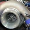
    • You just need to remove the compressor housing, not the entire turbo. I would not be drilling and tapping anything with the housing still on anyways. 
    • So, I put my boat on a boat. First of all, I'm going to come out and say it. Why is Tasmania not considered a holy goal, an apex that all road-legal modified cars go to, to experience? This place is an absolute wonderland of titanic proportions. If people are already getting club runs for once in a lifetime 30 person cruises to Tassy then I've never seemed to see it. It is like someone replaced the entire place with an idyllic wonderland for cars, and all of the people living there with paid actors who are kind, humble, and friendly. Dear god. After doing a lap of almost all of the place I've found that it's a great way to find out all of the little things that the car isn't doing quite right and a great way to figure it all out. All in all, I drove for 4 hours a day for a week and nothing broke. I didn't even need to open the engine bay. This is by all means a great success, but it has left me with a list of things to potentially address. I also now have a 3D printed wheel fitment tool which annoyingly hasn't got any threads in it to actually assemble it. I might be able to tape it together to check the sizing I actually want to use, but it'll likely involving pulling the shocks out to properly measure travel at least at the front, and probably raise the car while I'm at it, at least in the rear. I scraped on quite a few things and I'm not sure how else to go about it. I was taking anything with a bump at what felt like 89 degree angles. And address those 10 other tasks. And wash the car. God damn it is dirty. And somehow, the weather was perfect the entire time - And because I was on the top of Mt Wellington it turns out it was very much about to freeze up there. I did something I typically never do and took some photos up there in what must have been -10 and the foggy felt like suspended ice, rather than mere fog. If you own a car in Australia, you owe it to yourself to do it.
    • Damn that was hilarious, and a bit embarrassing for skylines in general 😂 vintage car life ey. That R33 really stomped. Pretty entertaining stuff
    • Hi, I have a r32 gtr transmission. Does any of you guys have an idea how much power it will hold with the billet center plate and stock gearset? At what power level and use did yours brake with or without billet plate? Thanks, Oystein Lovik
    • Saw this replica police car based on a Mitsubishi Starion XX parked next to a 'police box' (it's literally a box) in Hirohata, Himeji City in Hyogo prefecture the other day. It's owned by Morii-san who is a local Mitsubishi Starion enthusiast. According to a local radio station blog post, he always wanted to make a police car himself based on ones he saw in his favourite Manga comics.  As it's illegal to modify a car to look like a police car and drive on the road, Morii-san tried many times to get permission from Aboshi police station headquarters nearby. They refused initially by after they got tired of that they granted him permission. However, the car can only be displayed on private property and obviously can't be registered as long as the police livery is present. The car was completed at a cost of 1.5 million yen (US$ 10,000) in addition to the car cost. A location was chosen outside Hirohata Police box where the car can easily been seen from the street. Morii-san has two other Starion road cars, both widebody GSR-VRs.
×
×
  • Create New...