

Announcements
-
Similar Content
-
-
Latest Posts
-

By Murray_Calavera · Posted
My dream is also to have a proper hoist, but I don't think it will ever happen. My quickjack is probably as close as I'll ever get, it really is very good though. -
 Yeah we keep on in the dailies, it is pretty poor how many animals get hit and the driver leaves without checking....have saved a couple of little ones over the years. Bit of a gruesome job though, pouches generally need to be cut open because they are so tight and often the joey doesn't realise mum is gone so they are still locked onto the teat. I checked the modules in front of the DS wheel where an oil cooler should go.... There is the radar unit - that can go for race use) One of the 2 HX water pumps, the silver cylinder. That needs to be kept but might be able to be relocated But the bad news, the big computer mounted vertically in front of the wheel (blocking any potential air exit) is the electric steering computer. That is required until/unless i do a hydraulic steering conversion, and in CAD based modern car design it is not like I can just pop a big unit like that somewhere else (plus the loom would be too short anywhere else too). So, the passenger side is OK to clear out (just use a smaller washer reservoir, potentially elsewhere), but the DS no beuno
 -
Well, all the best with the new camry It was interesting to hear about the UK process, it is generally a lot more streamlined here with a shipping agent looking after all the import side (noting the exact final price can still be a surprise.....) and I've used a few different brokers on the japan (or US) side, and never had any trouble with any of them....luck of the draw I guess. You mentioned you didn't get the auction sheet (understandable since you bought it from a dealer, not auction), but I always try and get hold of that because they are pretty thorough. I've imported 2x R grade vehicles over the years and both were fine, repairs in Japan are pretty thorough compared to here in Oz.
-
BTW I measured the jack I have, it is 70mm at the saddle but you only have about 700 until it returns to 150mm high at the cylinder so it is good but no magic bullet.
-
By hoodedreeper · Posted
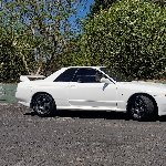
My experience with Rising Sun Exports Before agreeing to the sale I tried to do as much research as I could (obviously), his Facebook reviews are 98% and he goes Live at least once or twice a week. I contacted 2 people in the UK who had used him for their imports, both had positive feedback. His explanation and talk through of the import process was thorough, answering any query no matter how stupid it was. It felt as soon as the money was sent, communication dropped off. I asked for shipping updates every 2 weeks or so, not wanting to pester him, he never had any updates. I wasn't informed the car had been dropped off at the port, I only found out by his Facebook story. I asked for the photos taken at the port, knowing he would need some for insurance purposes. I received a few 5 second clips and that's it. When asked again, he said his staff had them. Weeks later I asked again, he tells me he doesn't have any, but does have 50 photos from the original advert. I never received them. I eventually got the documents sent via WhatsApp after I mentioned the port was requesting them. I purchased a CarVX report, to find out the vehicle is a Grade R with recorded accident damage, first recorded in 2017 when it was first auctioned. He never told me the grade, then again I didn't ask. His response was "Grade R means nothing, it wasn't chassis damage". Still, I would have liked to have been informed about it. Jon prides himself on being open and honest when it comes to inspecting cars, it's his main job doing so at the auctions for customers. When the vehicle arrived in the UK I noticed a few little cosmetic issues. It's a 21 year old car so it wasn't going to be mint condition. The side skirts are cracked on each corner and the sealant is failing. The front grill on the bonnet/hood isn't secured very well, mounting studs are missing. Both minor things, but again, it would have been nice to be told. During a Facebook Live walk around video of the vehicle, he mentioned it has a front Whiteline anti roll bar/sway bar. While on the inspection ramp, I noticed the stock item has been installed. When first questioned, his response was "the ARB? Switched? Since when, it never had them". Since sending video and photo evidence I've not received a response. I'm probably being over critical of the overall condition of an old car, but all I wanted was honesty (which he claims to have). I'm aware I wasn't his only customer, he's busy doing XYZ but other reviews praise him for great communication with regular updates and photos, I felt I didn't receive the same treatment.
-


Recommended Posts
Create an account or sign in to comment
You need to be a member in order to leave a comment
Create an account
Sign up for a new account in our community. It's easy!
Register a new accountSign in
Already have an account? Sign in here.
Sign In Now