
Announcements
-
Similar Content
-
-
Latest Posts
-
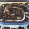
 The key takeaway is really about patience and angle management; getting the engine tilted back enough and the gearbox supported correctly makes the whole process way more manageable.
 -
Yeah, that makes sense - the area around the passenger suspension tower is usually pretty tight, but if the reservoirs and airbox aren’t overly bulky, a careful repositioning of that loom plug could free up enough room without interfering with airflow or access.
-

By Watermouse · Posted
Silly, You need to edit your posts with some “HA” quotes -

-

By Dose Pipe Sutututu · Posted
If go with OVO or similar, you can buy electricity off peak periods of the day for next to nothing, i.e. when the sun is out and everyone is exporting and noone is consuming. I'm also planning to join a VPP and sell back during peak hours. Bro science stacks up, and also the battery inverter has a spare MPPT port, so I could add another solar array. I still have the roof space for at least another 7 panels.
-


Recommended Posts
Create an account or sign in to comment
You need to be a member in order to leave a comment
Create an account
Sign up for a new account in our community. It's easy!
Register a new accountSign in
Already have an account? Sign in here.
Sign In Now