Jump to content
SAU Community

Recommended Posts

  • Replies 241
  • Created
  • Last Reply

Top Posters In This Topic

Top Posters In This Topic

Posted Images

  • 2 weeks later...
Hey Hows it going man, I live in canada, well Quebec, I have a R32 GTR and I'm planning on doing the same thing as you but different, what I'm asking is what website or provider did you use to get your parts, because I have a bunch of Japanese and American Sites, but the trunk is carbon fiber and so is the hood and stuff, and also the lights arn't included. I have a gerneral Idea of what I'm going to do with the front, but it's the back i'm worried about, I have to cut part of the back to get the trunk to fit good. Anyways if you can give me your provider via pm or on this post would be great.

What I need to know is where you got your

R34 GTR OEM Front Marker Lights(Flashers Yellow Light?)

R34 GTR OEM Rear Tailllights

R34 GTR OEM Trunk

R34 GTR OEM Trunk brake light

R34 GTR OEM Metal behind taillights Panel

R34 GTR OEM Back up Lights

R34 GTR OEM Aluminum Hood

R34 GTR OEM non-xenon Headlights

R34 GTR OEM Rear Tailllights

Thanks again man I hope you can answer me, cuz I'm tired of googleing and stuff to find a provider, thanks

Shawn

one short word, NISSAN

.. i ordered it all through my local Nissan Dealership. I just had to find all the part numbers myself with my Nissan FAST program i have on my laptop.

Any update since? Very nice conversion. I am currently doing an entire S15 conversion on my S14, the work entailed is quite similar.

give me one sec, im just uploading more pics.

so far, the rear end is pretty much done, now the sideskirts have to be custom molded, and thats about it. trunk latch assembly is being shipped... its one damn big job. not for the faint of heart, or someone with a limited budget, thats for sure.

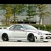
I know it isnt much of a big deal in Aussie, but Here in Canada, the R34 isnt legal, and isnt on the street. This will be one of the only cars in Canada that resembles an R34 At all... should fool alot of ppl at least on the highway and passing by.

worth every penny :thanks:

Image048-1.jpg

Image047-2.jpg

Image046-2.jpg

Image001-2.jpg

Image045-2.jpg

looks good.

The rear is much lower than a real R34, as is the R33 rear.

This is taking a very long time, must be killing you. do you spend every day on it? or is it a side project?

looks good.

The rear is much lower than a real R34, as is the R33 rear.

This is taking a very long time, must be killing you. do you spend every day on it? or is it a side project?

I think the rear was level with the body line... the r32 is more straight so we had to contour the rear to match.

the r34's body line starts rising near the side mirror and goes higher and higher till the end, but using that shape wouldnt suit on the r32, cause the tail end would start to point on an upwards angle and look even worse.

believe me, i want this done asap, but not 100% a priority

Yeah. Downside of a 34 anyways, but it gives it its distinct look, thats why the 33 to 34 looks different to a real one cause the body all over is lower from the roof down to the rear.

Ah well, good luck (Y)

Yeah. Downside of a 34 anyways, but it gives it its distinct look, thats why the 33 to 34 looks different to a real one cause the body all over is lower from the roof down to the rear.

Ah well, good luck (Y)

thanks, its not really luck, just time.

Coming along nicely,

Panel shops rarely do their best work under the pump in my experience, and if you're spending that amount of dough you'd want them to take their time and do the job properly!

Coming along nicely,

Panel shops rarely do their best work under the pump in my experience, and if you're spending that amount of dough you'd want them to take their time and do the job properly!

well the price would probably be alot more if I told them to hurry up, and focus this as their only project until its done. but bumps in the road happen, and things go on a standstill while new parts must be ordered to make the install as seemless and OEM as possible.

my new website will be online once the car is completed WWW.MWR34.COM

it will be the home of the complete build gallery, the photoshoot gallery, details of car, also this car will be for sale.

And future build plans for your custom-made MWR34 will be available. lets hope this turns out nice.

  • 3 weeks later...
  • 2 weeks later...
  • 2 weeks later...

Tell me what you think..

I took the dash from my Bayside Blue crashed parts car, and now making my own custom modified / fiberglass'd Dash board.

From the pictures I hope you can see where im going with it.

DAY 1

Dash cleaned and degreased

Image002-4.jpg

closer

Image003-3.jpg

guidelines and Center vent safely removed

Image004-4.jpg

closer

Image005-4.jpg

BAM!!! Cut off

Image007-3.jpg

Image006-4.jpg

Upper cluster tray

Image009-3.jpg

Back together

Image010-2.jpg

Image011-3.jpg

general look will be like this:

template.jpg

Create an account or sign in to comment

You need to be a member in order to leave a comment

Create an account

Sign up for a new account in our community. It's easy!

Register a new account

Sign in

Already have an account? Sign in here.

Sign In Now


  • Similar Content

  • Latest Posts

    • For once a good news  It needed to be adjusted by that one nut and it is ok  At least something was easy But thank you very much for help. But a small issue is now(gearbox) that when the car is stationary you can hear "clinking" from gearbox so some of the bearing is 100% not that happy... It goes away once you push clutch so it is 100% gearbox. Just if you know...what that bearing could be? It sounding like "spun bearing" but it is louder.
    • Yeah, that's fine**. But the numbers you came up with are just wrong. Try it for yourself. Put in any voltage from the possible range and see what result you get. You get nonsense. ** When I say "fine", I mean, it's still shit. The very simple linear formula (slope & intercept) is shit for a sensor with a non-linear response. This is the curve, from your data above. Look at the CURVE! It's only really linear between about 30 and 90 °C. And if you used only that range to define a curve, it would be great. But you would go more and more wrong as you went to higher temps. And that is why the slope & intercept found when you use 50 and 150 as the end points is so bad halfway between those points. The real curve is a long way below the linear curve which just zips straight between the end points, like this one. You could probably use the same slope and a lower intercept, to move that straight line down, and spread the error out. But you would 5-10°C off in a lot of places. You'd need to say what temperature range you really wanted to be most right - say, 100 to 130, and plop the line closest to teh real curve in that region, which would make it quite wrong down at the lower temperatures. Let me just say that HPTuners are not being realistic in only allowing for a simple linear curve. 
    • I feel I should re-iterate. The above picture is the only option available in the software and the blurb from HP Tuners I quoted earlier is the only way to add data to it and that's the description they offer as to how to figure it out. The only fields available is the blank box after (Input/ ) and the box right before = Output. Those are the only numbers that can be entered.
    • No, your formula is arse backwards. Mine is totally different to yours, and is the one I said was bang on at 50 and 150. I'll put your data into Excel (actually it already is, chart it and fit a linear fit to it, aiming to make it evenly wrong across the whole span. But not now. Other things to do first.
    • God damnit. The only option I actually have in the software is the one that is screenshotted. I am glad that I at least got it right... for those two points. Would it actually change anything if I chose/used 80C and 120C as the two points instead? My brain wants to imagine the formula put into HPtuners would be the same equation, otherwise none of this makes sense to me, unless: 1) The formula you put into VCM Scanner/HPTuners is always linear 2) The two points/input pairs are only arbitrary to choose (as the documentation implies) IF the actual scaling of the sensor is linear. then 3) If the scaling is not linear, the two points you choose matter a great deal, because the formula will draw a line between those two points only.
×
×
  • Create New...