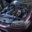
Jump to content
SAU Community

Recommended Posts

Hey guys,

Item: I have an AUTRONIC SMC HC WITH 500R CDI ECU with RB26 loom, high current injector drivers and auto tune 500R CDI ignition included ($1,100 alone) can supply matching CAS if needed, Mazda 13B turbo twin post coils x3 (3" spark!)

Location: Georges Hall, Sydney

Price: $1,700.00 ONO DELIVERED to anywhere on mainland Australia.

Condition: Fine. It came off Dave's (T04GTR) car. I bought it and never used it

Payment: Direct debit to my account, Or cash on pickup (if in Sydney)<BR style="mso-special-character: line-break"><BR style="mso-special-character: line-break">

PS: I bought this off Dave (T04GTR) a few months ago and never used it.

I will lay it all out on the floor and take a few photo's when the car isn't in the garage.

Link to comment
https://www.sau.com.au/forums/topic/385717-autronic-smc-hc-with-500r-cdi-ecu/
Share on other sites

Huge setup for the money. Here's specs for those interested;

USAGE

These systems can cater for the requirements of virtually any spark ignition engine, including the following: -

High output supercharged or turbocharged engines, with either multi point and/or

centre point injection.

Rotary (Wankle) and two stroke engines.

Engines having uneven firing sequences such as 2 and 4 cylinder ‘V’ configuration motorcycle engines and V6 motor vehicle engines.

FEATURES

Eight injector drivers for full sequential operation on engines up to eight cylinders. May be set for ‘semi-sequential’ operation on engines having more than eight cylinders, eg: - 12 cylinder engine using 6 groups of 2 cylinders.

All injector types catered for (0.9 ohm to 16-ohm coil resistance). Specify unit fitted with optional high current injector drivers for 0.9 ohm or twin injector applications.

User choice of manifold absolute pressure or throttle position as engine load input. Internal absolute pressure sensor for simplified installation 0 to 200Kpa (o to 29.4 PSI) and 0 to 300Kpa (o to 44.1 PSI) available from stock. 0 to 45Kpa (o to 66.1 PSI) available on request.

Single coil distributor, twin coil distributor or multicoil distributor-less ignition configurations are possible on most engines.

Fitted with environmentally sealed connector the standard unit is splash proof. Units are available with double environmental sealing for use in the most arduous of applications (eg: - rally, off-road, and marine).

Auxiliary output function that can be used for any of the following:

Closed loop (feedback) boost pressure control for turbo charged engines with rpm and temperature dependent calibration characteristic.

Closed loop (feedback) idle speed control.

Control of engine cooling fan.

Programmable on/off control for solenoid or relay driving that operates according to engine speed and load (eg: - can be used for gear shift control or light, over rev indicator, inlet camshaft timing selection or control of a supplementary electric fuel pump that augments mechanical fuel pump delivery at low engine rpm only).

Fuel used pulse output to electronic or electro-mechanical counter with resolution of 0.1 litre (or use with trip computer).

Or even more sophisticated control function such as servo control of auxiliary butterfly for turbo charged applications requiring precise throttle control and minimum turbo lag.

Exhaust oxygen sensor input for sensing air/fuel ratio. Connect the low cost AUTRONIC 02 Sensor directly or for more demanding applications the AUTRONIC Wide Range Air/Fuel Ratio Sensor and Meter. The low cost sensor requires no interface adapters or expensive air/fuel ratio meters, and offers moderate accuracy and tolerance to leaded fuels. This function can be used to monitor air/fuel ratio during engine tuning or can be used for feedback control of air/fuel ratio for applications requiring exhaust catalytic conversion (feature available on request).

Diagnostic/Error indicator of sensor or ECU fault conditions with memory for detection of intermittent fault conditions. An external light may also be connected for remote indication of abnormal operation.

Precise spark advance control strategy for both static and dynamic operating conditions.

Unique calibration strategy allows accurate control of fuel delivery under both acceleration and deceleration.

User selectable spark and fuel delivery strategy for abnormal engine operation conditions to minimize possibility of engine damage whilst still maintaining engine operation. (eg: - over heated or over boosted).

Comprehensive limp-home function with user selectable default settings that ensure engine operation can continue after sensor failure has occurred.

Full compensation of engine control parameters for engine operation at any altitude (fuel delivery, ignition timing and boost pressure).

Adaptive learning (with memory) to minimize the number of user setups required and to provide optimal control of air/fuel ratio, boost pressure and idle stability.

Rev limiter with a soft characteristic that uses a combination of fuel delivery and spark control.

Fuel pump safety shut-off. Pump stops 3 to 4 secs after the engine stops.

Unit is ultra light weight/compact yet has sufficient drive capacity for high power continuous duty supplications. (One unit OK all applications from motor cycle to large capacity twin turbo engines).

Optional interface unit to allow sequential operation without the need for separate crank/camshaft sensors or special multi-sensor distributor (P/N: - ADP102 available Q3-93).

Remote monitoring of all functions using optional telemetry adapter (available Q2-93).

INPUTS

Sensors

Ignition input Hall effect. (Also available for direct connection to magnetic reluctor type pick-ups).

No. 1 cylinder reference. (Also available for direct connection to magnetic reluctor type pick-ups).

Barometric pressure (internal to ECU).

Manifold pressure (internal to ECU).

Throttle position.

Intake air temperature.

Engine coolant temperature.

Exhaust oxygen (or optional Wide Range Air/Fuel Ration Sensor).

Adjustments

Idle mixture trim. (Internal to ECU and screwdriver adjustable from outside).

OUTPUTS

Main

8 off injector driver (optional 2 injectors per driver).

Ignition output

Open collector output to any of the following:

Single coil high-energy ignitions: Bosch 7 pin, Mitsubishi 3 pin.

Autronic Capacitor Discharge Ignition.

MSD 6A etc.

4 outputs are available allowing multi coil distributor-less ignition for application on engines up to 8 cylinders.

Auxiliary

Fuel pump/injector fuel shut off safety relay.

Multi function on-off or pulse width modulation output for either:

Engine cooling fan relay.

Idle speed actuator (variable duty cycle single pole type eg:- Bosch

Turbo charger waste gate control valve (SEM, most OEM types or AUTRONIC low or high capacity).

Turbo charger auxiliary butterfly control motor.

General-purpose duty cycle output with user defined characteristics.

Fuel used pulse output (for trip computer function).

SERIAL I/O

Communication with IBM compatible computer for calibration, fault diagnosis. (Some markets require special adapter).

MICROCOMPUTER

16 bit running @ 16MHz

SUPPLY VOLTAGE

Normal operation

Safe Limits

6.2V to 23V DC continuous

+/-24V (5 mins)

+/-80V alternator load dump (0.5 sec)

+/-1000V inductive spike (10 sec)

CURRENT DRAIN

@ Engine Idle

@ Max Engine Load

<1 Amp

<16 Amp (less depending on injector type and number)

OPERATING TEMPERATURE RANGE

Min

Max

-40°C

+85°C

ENGINE CYLINDER NUMBER SETTINGS

Number of cylinders

1,2,3,4,5,6,7,8,10,12,14 and 16

ENGINE RPM RANGE

0 to 30,000 RPM

0 to 16,000 RPM

0 to 15,000 RPM

Engines up to 4 cylinders

Engines 5 to 8 cylinders

Engine 10 to 16 cylinders

INJECTION DURATION TIMING

Min

Max

Accuracy

Setting resolution

0.7 msec

30 msec

+/-<(10 sec+1%)

0.1% approx.

INJECTION TIMING

Range

Accuracy

Setting resolution

0 to 720° (crank angle)

+/-<(1.4° + 0.3 msec)

2.8°

IGNITION TIMING

Advance range

Accuracy

Setting resolutions

FUEL DELIVERY AND IGNITION MAPPING

No. load sites

No. RPM sites

16 (max)

32 (max)

Both load and RPM sites are freely selectable

SIZE AND WEIGHT

L* W* H*

157* 122* 35*

180* 128* 35 mm (overall, including mounts and connector)

0.5 kg

CONNECTORS

36 way ‘AMP’ water and dust proof socket

  • 2 weeks later...
  • 2 weeks later...
  • 2 weeks later...
  • 2 months later...

Create an account or sign in to comment

You need to be a member in order to leave a comment

Create an account

Sign up for a new account in our community. It's easy!

Register a new account

Sign in

Already have an account? Sign in here.

Sign In Now


  • Similar Content

  • Latest Posts

    • Hi, is the HKS  Tower Bar still available ? negotiable ? 🤔
    • From there, it is really just test and assemble. Plug the adapter cables from the unit into the back of the screen, then the other side to the car harness. Don't forget all the other plugs too! Run the cables behind the unit and screw it back into place (4 screws) and you should now have 3 cables to run from the top screen to the android unit. I ran them along the DS of the other AV units in the gap between their backets and the console, and used some corrugated tubing on the sharp edges of the bracket so the wires were safe. Plug the centre console and lower screen in temporarily and turn the car to ACC, the AV should fire up as normal. Hold the back button for 3 sec and Android should appear on the top screen. You need to set the input to Aux for audio (more on that later). I put the unit under the AC duct in the centre console, with the wifi antenna on top of the AC duct near the shifter, the bluetooth antenna on the AC duct under the centre console The GPS unit on top of the DS to AC duct; they all seem to work OK there are are out of the way. Neat cable routing is a pain. For the drive recorder I mounted it near the rear view mirror and run the cable in the headlining, across the a pillar and then down the inside of the a pillar seal to the DS lower dash. From there it goes across and to one USB input for the unit. The second USB input is attached to the ECUtec OBD dongle and the 3rd goes to the USB bulkhead connected I added in the centre console. This is how the centre console looks "tidied" up Note I didn't install the provided speaker, didn't use the 2.5mm IPod in line or the piggyback loom for the Ipod or change any DIP switches; they seem to only be required if you need to use the Ipod input rather than the AUX input. That's it, install done, I'll follow up with a separate post on how the unit works, but in summary it retains all factory functions and inputs (so I still use my phone to the car for calls), reverse still works like factory etc.
    • Place the new daughterboard in the case and mount it using the 3 small black rivets provided, and reconnect the 3 factory ribbon cables to the new board Then, use the 3 piggyback cables from the daughterboard into the factory board on top (there are stand offs in the case to keep them apart. and remember to reconnect the antenna and rear cover fan wires. 1 screw to hold the motherboard in place. Before closing the case, make a hole in the sticker covering a hole in the case and run the cable for the android unit into the plug there. The video forgot this step, so did I, so will you probably. Then redo the 4 screws on back, 2 each top and bottom, 3 each side and put the 2 brackets back on.....all ready to go and not that tricky really.      
    • Onto the android unit. You need to remove the top screen because there is a daughterboard to put inside the case. Each side vent pops out from clips; start at the bottom and carefully remove upwards (use a trim remover tool to avoid breaking anything). Then the lower screen and controls come out, 4 screws, a couple of clips (including 3 flimsy ones at the top) and 3 plugs on the rear. Then the upper screen, 4 screws and a bunch of plugs and she is out. From there, remove the mounting brackets (2 screws each), 4 screws on the rear, 2 screws top and bottom and 3 screws holding in the small plates on each side. When you remove the back cover (tight fit), watch out for the power cable for the fan, I removed it so I could put the back aside. The mainboard is held in by 1 screw in the middle, 1 aerial at the top and 3 ribbon cables. If you've ever done any laptop stuff the ribbon cables are OK to work with, just pop up the retainer and they slide out. If you are not familiar just grab a 12 year old from an iphone factory, they will know how it works The case should now look like this:
    • Switching the console was tricky. First there were 6 screws to remove, and also the little adapter loom and its screws had to come out. Also don't forget to remove the 2 screws holding the central locking receiver. Then there are 4 clips on either side....these were very tight in this case and needed careful persuading with a long flat screw driver....some force required but not enough to break them...this was probably the fiddliest part of the whole job. In my case I needed both the wiring loom and the central locking receiver module to swap across to the new one. That was it for the console, so "assembly is the reverse of disassembly"
×
×
  • Create New...