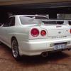
Jump to content
SAU Community

Recommended Posts

Looks great!

How do you join the two halves?

Structural epoxy adhesive. Put both halves back in the mould untrimmed, put the adhesive on the joint and then bolt the two halves of the mould together.

Have now infused the other half and filmed it this time, so for those that are interested, this is how I make each half:

Structural epoxy adhesive. Put both halves back in the mould untrimmed, put the adhesive on the joint and then bolt the two halves of the mould together.

Have now infused the other half and filmed it this time, so for those that are interested, this is how I make each half:

Damn thing didn't post:

https://www.youtube.com/watch?v=V71k0VNi-vU&list=UUrTGbs2Wk4T5hblvKod-5zQ

Also forgot to add, the total weight of the first half untrimmed is a hefty 112 grams, and takes all of my 85kg's standing on it without any distortion.

  • Like 1

Second half is now also finished. Didn't take any photos, but it looks the same as the first half :laugh:

Bought a - 10 Speedflow fitting for the breather return as well. Just waiting for my aluminium flat bar to arrive so I can bond it in, drill and tap it, then bond the two halves together and trim em up! Once I can fit it into the car, I'll work out my plumbing route for the bov return.

  • 4 weeks later...

Forgot to update this! I decided against the initial plan of bonding in a piece of 10mm aly flat bar as it proved too difficult to bend, instead decided to use a -10 Speedflow weld-on fitting which I scored and bonded in:

10152426_10151964043012541_2123605741419

1491654_10151964042952541_65765948613121
10169323_10151964043047541_5481263229588
I placed some woven fibreglass rovings into those grooves to help distribute any load placed on the fitting, then layed a piece of fibreglass over the top followed by an additional two layers of carbon fibre. The fibreglass is an important layer to separate the carbon and the aluminium, preventing galvanic corrosion.
10253919_10151964043132541_8646971665272
10171744_10151964043187541_5088805546055
Then bonded the two halves together using structural epoxy adhesive:
1978869_10151964043257541_78976412146382
Cleaned it up a bit, then polished:
10177941_10151964034577541_4907155736785

1606975_10151964034517541_59298124511784

10169446_10151964034442541_4053028006393

10262063_10151964034377541_8825594484521

It has been done, many times, just not so much with Skylines which does surprise me a little bit. If you're interested, PM me, I would be happy to make more for anyone interested.

Thought I'd post some photos of it all fitted up too:

603628_10151965716552541_522039540013891

10170918_10151965716797541_7351319015688

Had to be careful not to strain my back putting it in :P Final weight including the fittings is 193 grams. To give you an idea, the original stainless 3" pipe (which was also 100mm shorter) weighed 775 grams.

  • Like 2

Came out awesome! Does the bond between the AN fitting and the pipe have enough strength to tolerate the appropriate torquing loads?

As I mentioned before, if you make a 3" pipe to AFM, I'd definitely be up for one :)

Thanks guys :)

The bond definitely has enough strength, that fitting isn't going anywhere. To be honest, I've probably completely over-engineered that. In case you're interested, the epoxy adhesive that I used, Araldite 2014, is a structural adhesive which by itself has a lap shear strength of 19Mpa, or 2755psi. Then in addition to that, I've used the fibreglass rovings in the grooves I cut into the fitting to help distribute the load, and the reinforcement (layer of fibreglass and double layer of carbon fibre) behind it will also help absorb and distribute load. Realistically, you would destroy the fitting well before you even overcame the strength of the adhesive let alone needed the laminate around it, but I like to be sure about these things ;)

I've PM'd you by the way mate :)

Edited by Hanaldo

Create an account or sign in to comment

You need to be a member in order to leave a comment

Create an account

Sign up for a new account in our community. It's easy!

Register a new account

Sign in

Already have an account? Sign in here.

Sign In Now


  • Similar Content

  • Latest Posts

    • Bit difficult to follow. Have a look below and see what the standard R32 layout was like. Note there was a restrictor in place immediately before "turbocharged pressure control solenoid" that, if removed, magically got you 1 bar boost.
    • I might be way off the mark here.. there must be a T junction under the manifold. That takes manifold pressure through a check valve prior to the T, one side splits out to this bleed off orifice, the other straight to the wastegate actuators. 
    • Carrying out some engine due diligence before my first drive in a 260RS that has been in storage for 10+ years, and found two lines that are susposed to be plumbed into the boost control solenoid. One of the lines (the wastegate boost supply line) to actuate the gates, had a bolt in one end blocking it. The other line (main boost signal line) from the very rear of the intake manifold (RB26DETT) and runs up to the boost controller had this pill in the end of it as seen in photos. Other than the obvious (T28 Ceramic turbos might well be cooked)  Can anyone shed any light on if there is any validity at all with this mod, bleeding a constant fixed rate of manifold boost pressure off through this 3mm hole?  Is it deliberate?  Was this a 90s Jap mod done to RB26's? Or has someone just fitted this without any idea of what happens to ceramic T28s if they are not gate controlled?    
    • This looks great! Awesome to have the 5 speed with an LSD in this. The Recaro's look like SR2's or SR3's. It's a shame they've been retrimmed as they would have looked sweet in their original colours. I think I'd want my agent to be a little more up front and informative too. I've never imported but I reckon it would make me a little nervous, so the more info the better.
×
×
  • Create New...