
Announcements
-
Similar Content
-
-
Latest Posts
-

By soviet_merlin · Posted
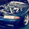
I'd be worried about having to parallel park a boat like that. Magnificent car though. -
 This car has run before on this z32 ecu can get the part number for you, I have tried with no AFM it didn’t change anything, I compression tested today 140-150 across all 6 cylinders, also set fuel pressure to 43psi. The only weird thing was cylinder 1 plug was black and fouled other 5 cylinders were just wet with fuel. Spun cas by hand and confirmed injectors are clicking
 -
 Since you came here to ask for help, have you thought about answering our questions, that might help us lead you to why it was skipping, or have you given up on getting advice?
 -
 A 1.5 way is a 2 way. It is just a 2 way with a less aggressive ramp on overrun.
 -
The ABS and/or TCS being missing/broken will not cause the engine to misbehave. It just casues CEL to come on and annoy you. The CEL is useless if it is always on, so you have to do the things you have to do to get rid of it, so it can be useful. Being a Stag ECU, then yes, it will not expect TCS to be present. But it will expect ABS to be present and working. You will need to either make the ABS CU talk to the ECU (don't ask me what that will take on an NA R34), and make sure the hardware is working....or, you just need to blank it out in Nistune. Do not persist with the stock ECU. You will just have problems. Gte it Nistuned. Start from there. DO YOU HAVE A BOOST SENSOR? The ECU's boost sensor that it. It is connected to the loom at the rear of the coil cover. Usually rides on the firewall on an R34, but is usually bolted down to a bracket along with all the other crap at the back of the coil cover when a Neo is dropped into another car. If you do not have it, the ECU will shit the bed. So, do you have one?
-


Recommended Posts
Create an account or sign in to comment
You need to be a member in order to leave a comment
Create an account
Sign up for a new account in our community. It's easy!
Register a new accountSign in
Already have an account? Sign in here.
Sign In Now