Jump to content
SAU Community

R33 Gts-t S2 - First Tuning Day - Gtx3582r - Tog Steam Pipe Parts Issues Found


Recommended Posts

Hi Guys, so finally completed my build and had first day of tuning friday 18th with Chequered Tuning - http://www.chequeredtuning.com

Firstly if anyone would like any images of mod's on the below article I would be more than happy to send more detailed ones through.

For those of you who dont know Trent and Catherine from Chequered Tuning - check their website and some may know Catherine as Driftcat and Trent is an excellent tuner and extremely knowledgeable as one could imagine.

Trent helped with certain aspects of choosing right items for the application and steering away from others - the only thing I forgot to mention was the Z32 AFM that I purchased tried to get the good old cheap cut corner type of ebay crap copy to save $180 or so and yep thats what happens on your day of tuning - throw it in the bin and - I have just driven over 250kms with the car on a trailer to find out that they are pretty much useless, then Trent and Cat say they have a friend just around the corner with a business and he would have one, so we walked just up to the cafe in the same building block as it was about 40+ degree's on Friday kicked back and had a bevo - and Trent and Cat arrive back within ten minutes - brand new genuine Nissan - and we are now good to go.

Trent did try the ebay crap one first but he did advise these are useless and they shouldn’t even be able to sell them on Ebay or anywhere,

And I also want to mention that his time on the Dyno is amazing - no time for talking haha - he works very efficient and still has great conversation while working.

3 Weeks ago

post-141798-0-27702500-1450576841_thumb.png

Day before Tuning

post-141798-0-11595200-1450576860_thumb.png

Large FMIC - 3" intercooler piping

GTX3582R Dual Bearing AR.82 – 11 Blade Billet Comp Wheel

TOG Steam Pipe Manifold – Tuned Length – 45mm External

Turbosmart Hypergate 45mm Wastegate

650CC Smartfire Injectors – Top feed Upgrade

345LPH in tank Topspeed Pro 1 fuel pump

Adjustable FPR

Z32 AFM

4 Inch Air Intake

Custom Plenum

80mm T/B

High Flow Air Filter

3 Inch Dump Pipe

High Flow 3” Cat

Twin Kakimoto Exhaust – Cat Back

Turbosmart Dual Stage Boost Controller

Greddy FV BOV

Plugs – Gapped 0.8mm - for initial first tune

Oil Catch can – Plumbed to Intake Pipe – PCV hose plugged

Alloy Radiator – Twin Thermo’s

Wideband O2 Gauge AFR – Bosch Lambda LSU 4.9

Boost Gauge

Apexi Power FC

Cometic Head Gasket
H/T Head Studs
Cometic Intake Manifold Gasket
Timing Belt Kit – Gates Racing – Idler and Tensioner Bearings
Alt/P/S Belt
Oil Pump
77c Thermostat
Fuel Filter
Thermostatic Controller

After day 1 in tuning some issues found - see below

TOG Schedule 10 S/P Manifold - Issues Found with the GTX3582R and Turbosmart Hypergate 45mm - Noted Below

post-141798-0-54474700-1450576879_thumb.png

Issues:

1. The wastegate is too far away from the collector and we want to have least path of resistance for stabilizing boost control

2. The piping size they use as you can see on the V Band Flange where I have marked in green has about 3mm or 4mm from the edge which means the pipe size is incorrect for the Turbosmart Hypergate 45mm - the pipe size used is OD 42.2MM & ID - 36.6MM and should be 45mm ID or I think it is 44.45mm that is available. - This is in their description 45MM WASTEGATE V-BAND FLANGE ( YOU CAN EITHER CUT AND WELD YOUR TYPE WASTEGATE ON OR YOU CAN USE TURBOSMART HYPER GATE 45MM FLANGE WASTEGATE)

3. Red - cut this pipe off completely

4. Blue Circle notch out an oval shape where we can form a nice 2 pipe to one flow at 90 degree - providing us with smoother exit of the exhaust gas to help stabilize boost

5. Yellow line is where the new 45mm V Band will be welded with correct merging of pipes into one at correct diameter

6. This will sit the wastegate closer to Turbo and having a better path for exhaust exit - and with this manifold the dump pipe and the Hypergate 45mm it will still fit nicely and either screamer out or can easily be made to enter smoothly at reduced angles to the dump pipe

7. When the manifold is completed I will post a picture

8. With this current setup on the TOG with GTX3582R and Hypergate 45mm - Boost came on pretty nicely set to 15psi for the base run and at a certain rev range - boost just wanted to get to 30psi as fast as it could - It climbed peaked stabilized at the set 15psi then after a certain rev range boost creep came on strong

9. In the next stage of tuning I will also add the outcome of stabilizing the boost levels - sometime around January 11th

10. Another issue that I had with this manifold is on the RB25det - R33 Series 2 - the number 3 cylinder exhaust outlet hits on the engine mount bracket that bolts to the engine - the black coated one - I simply marked out a curve where it was hitting and grinded/cut that edge out and plated just below to add strength - the part that was cut out is the structural bent edge on the top right hand side looking at the engine from the passenger side wheel - roughly 5mm needed to be taken out.

11. Other than that the manifolds are great quality just a few minor adjustments needed

12. Great Rocker cover clearance as we all know many manifolds dont have this because they are designed for smaller turbochargers - great shocker tower clearance as well just needed to adjust Turb housings

During the mapping/tuning and the boost creep wastegate issue - Trent also went up to Havoc Fabrication which is also in the same complex and had the fabricator come down to check the manifold - he took us to his workshop and showed us some very interesting items he is working on - the quality of these guys work is top class - he showed us some twin turb and twin wastegate setups and how they merge the pipes and have it close to the collector for maximum release. If you want custom turbo manifold work carried out check these guys out. He commented on the TOG and said its a really nice design just the wastegate outlet thats all.

POWER STEERING BOTTLE:

this was as simple as removing the bottle cutting the bracket on the right hand side - flattening the bracket out in the vice on one edge and folding a new edge - then bolted back to one of the original holes and drilling a new one and nyloc nut in the wheel arch - bringing the bottle around from the current position - in this picture the Comp housing looks close butfrom standing at the passenger wheel there is clearance - intake pipe was also purchased from the same company as the TOG manifold allows and has vacuum tubes welded in already, just needed to plug one off with a 12mm rubber plug

post-141798-0-03826400-1450576992_thumb.png

Oil catch and plugs for piping ends

with the 19mm rubber plugs the local shops here were limited so the person I sent to get the plug went to mitre 10 and came back with a rubber chair foot - worked that good did not even need clamp - very tight

post-141798-0-72544500-1450577009_thumb.png

MANIFOLD, INJECTORS, INJECTOR RAIL - this went together like clockwork cut a few pipes re-routed hoses, I also purchased a windscreen washer bottle from Burson's I just gave them a dimension of 100x100xH200mm - they had almost the perfect size complete with hoses switch pipe fittings cables (I didnt need all that but anyway)- the Factory R33 washer bottle motor fit into the new bottle I simply removed the new and put in the R33 - then I drill another 20mm hole and fit the secondary motor from the R33 and now I have the perfect replacement bottle both motors and excellent clearance for the new Manifold T/B and Intercooler Piping. Another modification I needed to do on the Intercooler piping just before the T/B was a 19mm tube for the IAC valve intake tube

post-141798-0-22655900-1450577023_thumb.png

THROTTLE BODY - 80mm T/B issue with the unit sticking open slightly at low revs sometimes 3000rpm - when you back off throttle holds open then a quick touch it closes - Trent loosened nut on side to see if it was excess tension - even placed a second return spring and it is still doing it - so Trent was able to tune to a certain point based on the previous boost creep it was limited for the tuning - I have pulled apart the T/B and checked now and found that the 2 bearings on each side of the shaft were pressed way too tight, when I had everything apart and only the 2 bearings and shaft in the T/B it was tight to some degree, where as a normal T/B should free spin easily. I pressed the shaft out and voila bearings free spin - reassembled with 0.5mm clearance and the bearings and shaft work great - installed back into the vehicle and test drove while data logging and the sticking throttle has now gone.

Z32 AFM - Make sure not to buy copy item on this - purchase the genuine Nissan AFM - This has been setup boost through on cold side mounted vertical below inner guard where the inter cooler piping comes out of Throttle Body (If you would like picture just message) - AFM Harness extended with 5c Trailer Cable and wire ran along the underside of the radiator support panel - reversion don't even notice it - and wiring for the Z32 AFM for R33 - Make sure you dont splice or join the 2 ground wires together for series 2 - 3 wire AFM to Z32 - the Z32 needs to have the signal ground to signal ground and the chassis earth as mentioned it is chassis earth for a reason.

post-141798-0-18815100-1450577043_thumb.png

BOV - Vented to Atmo and it is directly opposite the AFM but on the passenger side below inner guard mounted vertical - Vac Line from Manifold Behind T/B and ran along the drivers side and along the underside of the Radiator Support Panel

SILICONE INTER COOLER HOSES - popped a few off on the initial load testing once they were tight - boost away - I will explain below on this

SMFI INJECTORS - So far so good the Smartfire Injectors are performing very well - we have 650's in for now testing the performance of the SMFI type - and if needed we have 1000cc and 1200cc

FUEL RAIL - after I completed the installation of the fuel pump and were ready for its initial priming to test for leaks and pressure testing at different levels, when I first added pressure/flow 15psi - I had 2 fuel leaks - and this point was late in the early hours of the morning - yep fix it tomorrow, the next day I found the issue I had double O-Ringed all injectors and somehow had missed one injector with the double o-ring and yep the O-Ring that was on this one particular must not have had enough slippy stuff and one edge was flattened - when I replaced and doubled it perfect, so good lesson double check your double o-rings and ensure to add sufficient KY VAS LUBE OIL whichever you choose,

The second leak was in the AN 90degree fitting at the rear of the fuel rail - Maybe I over tightened - but this particular fitting I noticed when tightening it was moving around like it was slightly bent hence why it wasnt sealing - misaligned contact surface - changed it out and sealed great.

I then performed testing at 5 minutes intervals with 30psi - then the stock 43.5psi all seemed well no leaks - I continued to increase fuel pressure to 63.5psi and all the way to 80psi with no leaks in the system while running cold test. I was curious to see when heat transfer was applied in tuning. All went well

FUEL PUMP - Topspeed Pro1 345LPH In tank

Very easy conversion - unscrew everything take it out remove old pump fit new pump put back in - the only issue was the big black plastic nut holding the pump assembly into the tank, blow dust away with air, spray with WD40 so the threads get penetrated with lubricant, use a 3foot long piece of steel tube and a big whacker, slowly hit each tooth on the big black nut anti clockwise, it moves about 2 inches at a time until it is ready to unscrew by hand. Another note people say the black o ring needs to be replaced when removed because of expansion but just take your time be careful dont stretch anything and it will go back in with no issues and you wont be able to smell fuel in your boot, thats why we use WD40 so the Black Nut doesnt bind on the big o-ring causing stress and stretching it.

post-141798-0-00569500-1450577612_thumb.png

post-141798-0-17699000-1450577737_thumb.png

post-141798-0-35251000-1450578128_thumb.png

post-141798-0-34234800-1450578144_thumb.png

When the fuel pump is out you can either inspect the sock and use it - or use the new one - or purchase stock sock - there are many discussions about this but I used the new sock - the pump doesnt suck fuel from the lowest part of the sock - it is like a sludge pump so to speak it will lie across the bottom of the tank and if only if the end or half the sock was full of sludge which if you have this clean out your tank - impossible - but like in a dam with water and mud they will block 3/4 of the sock and still be able to suck through, some people see the long sock and think that the new pump with a short sock will only suck 3/4 of a tank of fuel and run out now with a shorter sock - not gonna happen unless you mount the pump 1/4 of the way up that steel bracket. Hope this helps most socks will fit the walbro and other universal in tank pumps - be sure to use the rubber surround and cable tie the pump - I also used the rubber base plate and cable tied it into place as well.

Another one in discussions is that some people ask about the wiring in the tank and worrying about sparks and earth in fuel - dont stress their is no metal or earth other than the earth wire - use the standard terminals they give you with insulation - you wont get spark jump from the terminals unless you have serious amps like tig welding or coil packs and dodgy wiring - the wire is submerged in fuel so no spark jump - I used solder and heatshrink and small cable ties to clean wire to bracket and the tank is not earthed or made of steel.

Intercooler Piping

This was a matter of choosing the right bends and pipe size for the application - I found a company AUCXRACING where you can choose 6 bends of any degree and size, 6 silicone hose joins of any type and 12 T Bolt Clamps all for $119.00 - I chose 3" all the way as it was easier and less reduction from turbo to throttle body, just took maybe 20 minutes after everything was ready and in place for the piping to work out bends and silicone joins - with this front facing manifold and R33 with the Top Mount GTX3582 - 80mmID T/B was 3 1/2" to 3" Straight Reducer 70Degree from T/B downwards then AFM into 90degree - 90degree into intercooler - from the turbo to intercooler is 2 1/2" to 3" 90degree Silicone Bend Reducer to 90degree into straight silicone 3" into straight 3" BOV Adaptor with straight silicone on each end then 90 and 90 into intercooler. Bottom line was 1 x 70degree 3" Alloy Bend and 5 x 90Degree Bends

post-141798-0-28196200-1450579218_thumb.png

Oil Return Line from turbo

This was custom manufactured to suit the GTX3582R in the position I have it - I wanted as much steel tube from the turbo to the return inlet on the stock pipe - here is what I had done - on the stock turbo it has a 45deg oil return tube on the turbo end - I cut the standard mounting bracket/flange off and now I have a perfect 45deg bend for this setup - I traced the new GTX3582 oil return flange size onto some mild steel plate and cut and drilled out - took about 5 minutes - then for the rest of the steel tubing on the standard R33 RB25det as below in image marked in red - cut this off and used for the rest - I welded the 2 pipes together - the joins length and angle was dead inline with the oil return on the engine - Now I dont need to stress on rubber tubing too close to turbo - it has about 150mm section of rubber right down the bottom.

post-141798-0-19303500-1450577262_thumb.png

post-141798-0-84000600-1450577273_thumb.png

Or you can buy this type - In the kit I purchased it was manufactured for GTX3582R for RB25det but only had the Oil Feed, Water Feed and Water Return all in braided - but missed the kit with the oil return - so just used some brains and manufactured - good to have all the tools

post-141798-0-12948500-1450577288_thumb.png

Turbo Smart Wastegate - Hypergate 45mm

Anyone needing to setup with manual dual stage see below - switch in car on accessory power

post-141798-0-23176700-1450577374_thumb.png

There are many other small mods done while putting the new upgrades on like dump pipe using stock 3" and adding only a couple of extra insert pieces with the 4bolt flange, AFR wideband install, screamer, water hoses under the plenum, injector loom extension and fitting the EV1 plugs, the PCV valve has a dummy tube plugged doesn't actually do anything all vents through catch to inlet, removed all AC unit components,

Injector loom on the underside of the plenum - I found it easier to run the injector loom down between the runners as in image feed the back three then the front three - trying to run the whole loom from the front or under the side down near the fuel filter side is impossible with all the piping and IAC and other - also front is very restrictive with the water neck - you will need to extend the injector plugs with wiring to have the loom on the underside of the plenum

post-141798-0-00919600-1450579502_thumb.png

Removed factory boost solenoid located near power steering bottle and sensor - ECU does not require these at all they are only for factory boost setting for the stock turbo and the sensor on the drivers side just near the brake booster is only for the factory boost gauge.

Hopefully I caught some things in here for anyone upgrading or using certain parts in their builds.

I will also put up the Dyno runs when I have them all together - there are a few numbers but with the sticking throttle at tuning along with the wastegate boost creep obviously we know it is no way safe to run the full testing - at moment has 225kw with 351nm and the second reading was 298kw with 450nm - boost was coming on at about 2500rpm - from 4000 to 5500rpm was 15psi and held through to 5500 rpm then from 5500 to the 6500rpm was 24psi - and in the time it takes to see this and take off throttle is very quick

I think with the next tuning day the low boost will hit the same mark and stabilize right through the full rev range

The second boost or high boost setting should hit the full mark between 4500 to 5000rpm as the linear curve in theory from looking at my sheet will continue along this curve line.

Around January 11th to 12th should be the next tuning day and will upload results

Edited by tuning_vs_hardware
  • Like 1
Link to comment
Share on other sites

Shit yeah!! Catch up with you sometime this week man ;) was reading the description like "huh? I know that setup!!" :P

Yeah should be good Nick - gotta get some argon tomorrow for the tig and some sched 10 steam pipe bends - then pull it all apart to cut and weld the wastegate tube - pm if ya want to catch up before xmas will be home or at workshop most days.

Link to comment
Share on other sites

Yeah sweet go man, dont wanna hassle ya before christmas though. haha I keep forgetting its nearly christmas. f**k me man that list of mods....you didnt do it half assed that thing will be f**ken bulletproof! Im frothing at the mouth to see this thing in the flesh

Ha thats funny man - Christmas is only another day on the Calender sounds like your preaching to me. lol The only thing I did was covered everything for this stage of upgrades, fuel and air. as far as being bullet proof again that all comes down to how you drive them and what tune is in the car. We see many people saying they have big amounts of power but it also comes down to what your going for, track car, dyno queen, burnout pig, drift king, drag car, show pony. they all have there own uniqueness and characteristics - there are guys in the big smoke running 7 second daily drivers. But as far as this stage of mods goes yeah its coming together and looking forward to its next tuning day

Link to comment
Share on other sites

If you get the time you should, well worth a read. Really informative, gives a great breakdown of the whole process, shows some good ways around dilemas and some good ways to do things, ill vouch for him and say this guy knows his shit! Your an admin aren't you?

Link to comment
Share on other sites

I have now completed modifications on the TOG manifold and have the vehicle back together - I would like to note the following that I have noticed after the new modifications - boost has now stabilized right through the rev range at the low setting 15psi and now doesnt have boost creep.

See below images for mods on the manifold

TOG Manifold ready for the old wastegate pipe to be removed

post-141798-0-26721300-1451206430_thumb.jpg

New piping for the Turbosmart Hypergate 45 - I chose 2" or 50.80mm ID Schedule 10 304 3mm Wall - as you can see larger diameter to release exhaust gas over the total flow of the 6 cylinders into one collector compared to the original 36mm tubing

post-141798-0-03027600-1451206431_thumb.jpg

post-141798-0-77385000-1451206431_thumb.jpg

In these 3 images it shows the standard hole size after the piping was cut off and how the original pipe was offset to basically one tube on the collector.

You can see even how restrictive this would be as it would try to release exhaust gas over 6 cylinders and try to exit out this small diameter - obviously lower boost and revs were able to stabilize it - but at higher RPM and Boost the exhaust gas would try to find the path of less resistance and being forced more out through the turbine and 3" Dump - Hence Unstabilized boost

post-141798-0-56645100-1451206432_thumb.jpg

This image - I have taken a measurement of the inner guard (Shocker Tower) and simply clamped a rule into place to ensure that when I manufacture the new piece I know there will be shocker tower clearance - also have the turbo bolted up to ensure there will be no clearance issues. Alternatively I could do it all inside the engine bay as Tig Welding we have no spatter - as its only a wastegate tube and small size not too extensive but easier to have plenty of work space in the manufacturing area and have a simple dimension for clearance. Tack up quick refit before final weld

post-141798-0-15207600-1451206433_thumb.jpg

New hole has been cut with a holesaw in the drill press - I also had to weld a small piece over the original hole because the pilot hole needed was right where the other tube was cut out - this allowed the holesaw to be used - I didnt want to plasma cut this - also less cleanup after holesaw

post-141798-0-72938400-1451206433_thumb.jpg

New section machined with correct angles to get a nice tight fit for welding - this took a little amount of work to get correct angles needed, With the original Turbosmart V Band for the 45mm Gate - I needed to machine the inner surface for the larger diameter tubing - it was machined on an angle - in the image you can see the standard V Band Flange angle and the flat section across the top facier - this is standard and I machined it all the way to the outside edge to ensure smooth flow after welded onto the new tubing. Basically the outside diameter of the V Band on the top face is 1mm difference to the Inside Diameter of the Sched 10 pipe

post-141798-0-44028700-1451206434_thumb.jpg

New pipe fitment before welding

post-141798-0-17019300-1451206435_thumb.jpg

Completed manifold ready for fitting - wastgate tubing slightly angled upwards then down - you can see it curves up then down towards wastegate end - this allows a smoother flow rather than straight out at 90 and 90 degrees

post-141798-0-59703700-1451206435_thumb.jpg

I also wanted to post this as the original post the image wasnt really that clear - power steering bottle bracket relocation - used original bracket as mentioned - cut one side off folded flat and put another bend in - took about 5 minutes - for those who are looking to relocate bottle from the standard position - I also used a 12mm and 19mm hose joiner and some hose to suit to extend.

post-141798-0-28348700-1451208756_thumb.jpg

Also need to change the current boost gauge as it is only a baby Autometer Pro Ultra 20psi to a min 30 - should get this done in next day or so

Next job fix new oil leaks coming from what appears to be the new Camshaft Seals

After these jobs are completed - Cant wait until week 11th January when it has its final tuning and power run on the Dyno.

Link to comment
Share on other sites

Today I pulled the engine down and found that a brand new camshaft seal has issues, the inner surface or sealing face had actually pushed outwards in one section. Definitely wasn't like it after the first assembly

Obviously causing a pretty good oil leak down the front passenger side of the engine.

Im not concerned on this but more why it has occurred after first assembly during tuning.

I have removed the PCV and installed Catch Can - crankcase pressure should easily vent through the rocker covers and intake pipe with no issues I would presume - I would find it hard to believe that with no resistance on the rocker cover ventilation that it could blow a cam seal.

post-141798-0-34396700-1451296005_thumb.jpg

post-141798-0-17663800-1451296008_thumb.jpg

post-141798-0-56753000-1451296008_thumb.jpg

post-141798-0-24703700-1451296009_thumb.jpg

post-141798-0-61991100-1451296009_thumb.jpg

post-141798-0-14937700-1451296010_thumb.jpg

New Seal fitted

post-141798-0-45782000-1451296010_thumb.jpg

Engine is all back and ready now just waiting for some curing and tomorrow will run the engine bleed coolant system and check for any leaks

  • Like 3
Link to comment
Share on other sites

Excellent - happy days cars all tested - systems bled no coolant or oil leaks - test drove for about 20 minutes after vehicle reached operating temp - only issue is the crap vacuum hose

Where the Brass fitting is on the rear of the comp housing gets too much heat for the vacuum hose and simply bursts at high boost.

post-141798-0-78706000-1451398095_thumb.png

Fix: Use heat resistant braided vac hose

Link to comment
Share on other sites

  • 5 weeks later...
  • 2 weeks later...

Just thought I would update this post, my younger brother is putting together a skid car with some new fresh paint. He thought he would get a bit creative with the 3M fine line tape on yes thats right my Skyline. We are painting his skid car in Silver Base, 375 micron Metal Flake, Taped off the silver flames still undecided on graphic or airbrush - but either way he has the DNA Silver Holo Flake and DNA Candy Red. So he gets there and starts to tape flames on my Skyline and the next day I came in to see green lines on my car.

Around lunchtime that day he walks around the corner and say's you better come check the graphics on your car with a weird look on his face. When I walked around the corner here are all these lines where the Tape had removed the top coat all the way back to primer. LMAO - i think he wasnt sure what my reaction would be - hey its only paint.

post-141798-0-42798400-1455451895_thumb.jpg

post-141798-0-04274300-1455451914_thumb.jpg

Bonnet roof and boot are ready to go all primed - affected tape area's have been fixed - I noticed that the previous prep work was the issue with the paint just ripping off with the tape. The primer had a shiny finish and I believe who ever painted this vehicle prior had maybe wet and dried the roof and bonnet to a shiny finish with maybe 1000grit or higher - there was definitely no chemical or mechanical adhesion with the top coat - it was pretty much just sitting there all these years.

All top coat on the bonnet and roof has been removed back to primer - and have performed a cross hatch test to see if the primer has adequate adhesion.

Its funny that the roof and bonnet on the vehicle had been originally resprayed and an absolute crap job, still looked ok and shined and blended with the rest of the car, but noticed slight paint edges on the rubbers where it was taped off.

The factory paint was still in pristine condition. Makes for an easy respray when the vehicle is so straight as well.

So looks like now I am full respray on my car.

I already have the 2K Primer, and Clear over Base ready to go. I have chosen the standard QM1 color white and had them alter it slightly, I am also applying White Pearl Metal Flakes over base coat then White Silver Pearl on top followed by liquid glass diamond clear. Should provide something better than just standard white little sparkle not too much and a slight darker shade like a silver/white and bright on the edges that are hitting the light more.

post-141798-0-57348100-1455453177_thumb.png

Inspired stripe color by this Matte White Ferarri - I love this car, with regards to the website hosting the images http://gtspirit.com/2015/10/05/matte-white-ferrari-458-speciale-with-redblack-stripes/

post-141798-0-18192200-1455454594_thumb.png

Stripe sizes still undecided - when the Flake arrives we will be painting about 27 test cards with the different coating thickness to see how many Coats of flakes and pearls.

Black stripes and not yet sure if we will use the red flake on top or choose for a candy over chrome system to give it that anodized look with flat or choose for gloss. Car will be gloss finish not flat white or flat clears like the Ferrari - even though they look pretty amazing on certain cars.

Its unique when custom painting and choosing colors and graphic or air brush etc, you start to think will it look good or crap. But the main thing is test test test then go with it as long as it makes you happy and I like it thats all that matters.

Like they say in the custom world you are only limited by your imagination

So looks like the second Dyno appointment can wait for another couple of weeks.

Link to comment
Share on other sites

Got the 2 front guards complete ready for paint today that now completes roof, front guards and boot - also today managed to get the passenger quarter panel ready for primer, this leaves the driver side quarter panel and the 2 doors then the body is complete and ready for base coat. After all this is complete I will shift onto the side skirts, front bar rear bar and boot spoiler - If I can get a GTR Spoiler in time I will go with that - if not I will not doubt use the current one I have or just go with out and plug the holes temporarily with blanking grommets until I get the GTR spoiler. Ideally painting it all in one go is better to ensure correct metal flake and pearl coverage - but if you have the exact ratios measured by volume and weight - the gun is always set to the same position with pressure and fluid - and the only thing that leaves is the distance speed and overlap.

post-141798-0-73813700-1455713790_thumb.png

Today I also cut the 30 test spray cards 100mm x 100mm in composite panel - light sanded with orbi and primed ready for the white base coat and black base coat

I marked the back of each card with the coatings for each to ensure they get the exact coats

The white cards are as follow

1: White Pearl Metal Flake 1 coat 2 coats and 3 coats

2: White Pearl Metal Flake 1 coat 2 coats and 3 coats and each with one coat of White Silver Pearl

3: White Pearl Metal Flake 1 coat 2 coats and 3 coats and each with two coats of White Silver Pearl

4: Some extra cards with same 123 coats with silver flake 123 and pearl 123

This image is just with the White Flake and no clear coat or pearl - that why it looks so flat

post-141798-0-62747500-1455714392_thumb.png

For the black cards - Black Base coat are as follows

1: 375micron Red Metal Flake - 1 coat 2 coats and 3 coats

2: 375micron Red Metal Flake - 1 coat 2 coats and 3 coats with 1 coat of White Pearl Metal Flake

3: 375micron Red Metal Flake - 1 coat 2 coats and 3 coats with 2 coats of white Pearl Metal Flake

The black cards also vary with 1 and 2 coats of the White Silver Pearl over the top

All up there are roughly 30 cards - when I have some clear over the top after I finish the silver flake and pearl - I will take some good quality photo's and upload them - I might even start another thread in the painting forum. Will have these completed tomorrow and make the choice on how many coatings.

Flake painted with Devilbiss SLG 1.8

Base coat Pearl and Clear coat painted with Devilbiss GTI Pro 1.3mm TE20 Air cap

Should look better than just standard QM1 white base coat

Link to comment
Share on other sites

  • 1 year later...

Hi Peeps,

Just thought to update this thread, been a long while since posting on it with some updated progress. As you all would know we get so consumed with work and other things and becomes a battle to work on our own projects. Anyway will do my best to explain what progress has been done since last time.

The last post was pretty much the vehicle first coats of high fill - and as you all would be too well aware lots of sanding and prep in between all the other, just to get the vehicle ready for paint work. Hah then when we get to the final stages and we get the odd cut through while sanding, yep more paint and finally ready for its clean down prep ready to put in the booth. I can't believe I just pushed 18+ months into a few sentences. Wow the long days nights and weekends

As you get further through the images you will see some changes were made, rather than just choosing a color scheme and running with it because in our heads we think it will look great and in actual fact could look quite silly on a vehicle. Also I didnt want to just hope it looked good - so a lot of testing and painting sample cards and panels just to get the desired effect I was looking for. And when we go custom 3 layers and 3 layer effects standard basic procedures are pretty much out the window.

The challenge was on thats for sure, after doing a lot in the past and working with candy pearls flakes and that over the years, the confidence was there but we all still second guess our process, constantly making sure we have everything covered even down to that last little piece of tape we apply during prep, up to the cleaning and making sure we minimize static as much as possible.

Well time to put up some images and show some progress. I will explain as I go

1. Early days masking off and hitting it with primer high fill to get ready for the blocking sanding to ensure any little imperfections are gone. The joys of having a reasonable straight vehicle meant no serious body work. Mainly just the door handle area's had slight low spots, from memory one small stone chip dent on the passenger door when a guy cutting grass shot a friggin rock at me, Just trying to keep the body lines and edges throughout the sanding was probably the most important. As long as you stay away from all edges and just work them very slowly. Was a challenge but enjoyable

IMG_0896.JPG.30a735c84f5b74f3d5b708b297ec4a0d.JPG

IMG_0912.JPG.355f163427bada1ad332c155bb595e08.JPG

IMG_0897.JPG.52812ab62e5a4b570ba848d14929be97.JPG

2. Bonnet had 2 very small low spots back left drivers side and front right passenger side right on the body line of the bonnet

IMG_0931.JPG.0b5d50c80bba83ffef4a81dbcc574e48.JPG

There were a lot more images in between this but I guess you guys would get a bit bored seeing all the images in primer and stages in between sanding, more sanding running through the grits - the initial sanding with with orbital all dry sanding, and using the softback interface in certain area's. After the initial orbital work. I made the decision to wet sand. Originally I wasnt going to - but it got the better of me and done it all with 800grit - not too fine so we dont get any de-lamination. Basically 400 grit all over and then 800 grit all over. Now ready for some color

So it all comes down to this, all that long hard work and prep - like they say blood sweat and tears. And a little bit of $$ - some like blue and some like pink we cant keep everyone happy. But as long as its what you want and like that all that matters.

3. All inner panels and jams were painted first obviously. As you can see we prep everything like we are painting all the parts we dont see when the vehicle is back together. Taping is quite enjoyable because we know its so close to being time to paint. Using the various methods of hard and soft edge so we dont get visible paint lines in area's we dont need.

IMG_1044.JPG.c4fa37ab3cb4f5b553e68431c1126111.JPG

IMG_1047.JPG.dffb892744000587899d2cfcecf3b64d.JPG

IMG_1050.JPG.586852dc591fbfb3365d9f70f69e799f.JPG

Time to hang some panels at this stage - basically all this was complete and baked off at 60degree's then straight into hanging the panels so we can remove all tape that we need to then tape it all off again.

4. So by this time is when it starts to get pretty exciting - all that hard work is finally coming down to this. In this first image I have layed down the QM1 white base coat and then hit the vehicle with its 2 final coats of white silver pearl. Now ready for taping off and its about 12:30am The reason I hung the front and rear bar like I have was to get that even blend of the pearl. You cant see in this image but directly beside me is the rear boot spoiler which is also coated at the same time. Basically perfect even coats with no double coats like we can get away with using basecoat or clear. If you double up on candy and pearl it will stand out, so some area would appear to have 3 coats etc etc. Tight overlap of 75% from bottom to top and all the way over and down. like painting a box and not following the body lines/shape. Full length from front to back along the sides.

IMG_1061.JPG.711cca6ec5756dd0d76fb366b97de639.JPG

Look at that pearl on the white - just makes it stand out as you guys know white is white but when we add something special it can look pretty good.

IMG_1063.JPG.a9c3f3e478fd1971e1a13667c80fbe82.JPG

Ok so now its about 3:00am and I was getting fairly well spent at this time, 8:00am start and yeah all day - 3 or so hours to tape off. But I actually sat back and reset myself and said you know what this part needs to be as good as you can get it, dont rush and just enjoy it. Only happens once. And that helped get these stripes the best I could given that I was by myself - Anyway before the spraying I had previously made my own templates for the boot back boot front, roof back roof front and same for the bonnet. Helped a lot doing a trial run before booth time. But the problem for the roof was my intention was to poke up through the sunroof and tape them off. But I couldnt disturb the clean car because we try to minimize dust and crap. So I made the choice to tape from the sides and ends. Not too bad at all.

IMG_1068.JPG.d53e2c077898ed2016fa3b81c4d90399.JPG

You will also see slight green fine line tape - thats how everything was initially taped to get the stripe edges perfect. Then simply tape everything else off.

IMG_1069.JPG.d3cba35d2a16d54f0ddd16ac6869c279.JPG

IMG_1071.JPG.0bab4c8f2ab99a87a1b525de66b804d1.JPG

Silver Basecoat which is the stripe edge lines.

IMG_1072.JPG.10d1709a772c77ea49e32896ab10642e.JPG

And yep had to run another fine line all the way across the vehicle after the silver was painted. Before apply the DNA Black basecoat which will become the main base for the stripes.

IMG_1076.JPG.7420b2079e67cf24db92a528d92a01f8.JPG

Now in between here were some images not taken, wow was I in for a surprise. By this stage its about 4:00am and I layed down the blue flakes. If I had to do it again I would coat the complete vehicle with intercoat before applying the flake stripes. Just to protect that pearl and I would definitely double mask off next time. So I could minimize and chance of flakes getting in places and working there way out. So you could probably guess - when unmasking all this ready for the clear coats. The flake on the masking was falling off everywhere. Took maybe 2 1/2 more hours to unmask, clean and blow away flakes and then mask it all back up for clear coats. 6:30am - time to go home and reset - have a coffee and rest.

IMG_1077.jpg.dafbad7463c5e5b59f5560eeeae4dffb.jpg

Back in at 8:15am - masked off and ready for the clear coats. As you guys may know we have a certain window time frame from first to last coats to get the clear down and seal all the hard work we have done. 24 hours. On the first coats I wanted to make sure to cover the blue flake area's first just to seal any stray flakes that want to blow off. So I gave the stripe area 1 coat first - then let it flash off and proceeded to coat the entire car with the first medium wet coat. Also just so you guys know I hit the stripes with 2 extra coats just to get some clear setting for when I flow coat it all out. And the entire vehicle was 4 full coats and 1 medium wet. This allowed enough room for perfect smooth stripe line edge and mirror finish across the flakes. Ensuring we have enough to cut and stay away from the pearls.

IMG_1085.JPG.76cd9aded3ff8ec59994c341f19befcc.JPG

IMG_1092.JPG.e492fc22c7a5c691b9c8253c9c18d71d.JPG

IMG_1094.JPG.64c346f04aa9c56e4be580509a586a9c.JPG

IMG_1103.JPG.5e82050eac25cd855af62ffc019c9d3f.JPG

5. Thought to share this image, as you can see being that the 375 flake a reasonable coarse. We tend to get a lot more orange peel - and also along the paint edge stripe lines

IMG_1109.JPG.33544d443ea2878c90613fa7eaa7d604.JPG

6. So your probably thinking or not - anyway I'll tell you a day before painting I was having doubts about the stripe choice - so I made changes and not painting a sample to see what it looked like added to the unknown. Just visually thinking what it would look like. Originally I was going with 8inch stripe with 2 inch black - so from Blue flake straight to black - which made the stripes 10 inches wide and a 2 inch centre line - so yeah changed it up moments before taping off. Again whats with the imperial measurement - I was inspired by a Mustang and took a liking to the stripes on this thing. Here is the original sample cards or test panels I painted - just to see with white pin lines and blue straight to black .

59ab9bae9014d_RacingStripe-BlueMetalFlake-OverBlackBase.thumb.jpg.19f3c1a88e2c88dcf640c1eca033facc.jpg

It was playing on me a bit and made the decision to go full blue flake with that silver edge line. I was happy that I made that choice.

7. Just a few pics after it came back out of the booth and some slight assembly. From left to right on the back of the vehicle.

IMG_1112.jpg.9c617ac7af6ca3cfd6d8adac47aeb72a.jpg

IMG_1113.jpg.28646f2d903c12677c9d82cd47679cb6.jpg

IMG_1114.jpg.8b419e123beef067ab2ad2f219e3aa47.jpg

IMG_1115.jpg.64cd1e0d39b2557309f97ff36fcbd2a7.jpg

IMG_1116.jpg.8961e95e5ea698e9d79a0c6f6085a501.jpg

A little bit of extra detail in the Garnish. Turned out pretty good for half hour of taping off.

IMG_1140.JPG.39030bcfb06761975f56cf580ebbfef5.JPG

8. Ok so some people probably wouldnt post this stuff up, being that we all thrive for perfection. As we know it either paint too dry and have massive ornage peel or find that balance of getting it to settle in better. After 5 coats of clear all was going great and that last final coat I slowed down even more and managed to get a hanger across the back quarter panel. Just thought to share these on the cut back. Using this method helps to get it all sanded down even - cutting the run out without cutting into the surrounding paint and making further work or sanding ripples into the clear. Build it to the top of the run keeping it tight, feather out all edges initial sanding with 400 grit jut to take the top off and get that smooth level then 800 grit - just working it as if you were flat block sanding anything and working it all even until it all gone.

IMG_1596.jpg.b84d27ee7c2cfb6285b07f12d779003a.jpg

IMG_1600.jpg.59c89588aae3678b9221610357697c27.jpg

IMG_1605.JPG.c91ac5caf3c0b500d6481035c112f234.JPG

IMG_1606.jpg.403992e4c9be71a180a9836ffa3814d1.jpg

IMG_1609.jpg.16250f233ff32c1a8218571e0b45d137.jpg

IMG_1610.jpg.c17a7b2f84521c2fde3df62380482c47.jpg

Gone flat smooth and happy with that

IMG_1611.jpg.7865af980cc66a27c7cb2d18ec905f57.jpg

9. At this stage the vehicle sat for about 2 weeks and then it was time to start flow coating. 800 grit from start to finish. All wet sanding and staying right away from edges. we can afford a cut through into the pearl, and cutting back the stripe edge lines and the flakes was also a bit of a challenge. Just hoping not to hit color or flakes.

IMG_1581.JPG.f548dd74bd22504fa4d3e556f38595aa.JPG

IMG_1582.JPG.845903527e0383af9c4dee7852727ebe.JPG

Sanded the entire car first then worked the front and rear bar last, on the first prep of the front and rear bar felt like it took longer that the damn car iteslf. So many angles to work and not many areas for flat block - soft back sponge worked in some area but others were all mostly by hand and very careful.

IMG_1585.jpg.5f4a25dd1ad28a9ac56e74d7d57f1414.jpg

IMG_1586.JPG.ebd4d515dea0d2d44e495b96695f7bae.JPG

After sanding the rear bar and cleaned down - got that nice even coat of water just to see how the clear will settle down in the booth. And its like a mirror. Looks pretty good

IMG_1617.JPG.695e68df05939b5f42c011e2a7f86ed6.JPG

Another shot with the water across the rear bar. Further down I also took this same image after the DNA Diamond Clear was put down.

IMG_1622.JPG.72a55444df8c8006ca9bcfa7c4e486e0.JPG

10. Finally all sanded back flow coating time ready and the thought of having to tape and clean it all down - Hmmm yeah I did mention that taping off is enjoyable but the thought of it was not so much. In the booth though its quite different because we are so damn close to sealing and finishing it all off for its final assembly. Anyway guys here are the last images of booth time and laying down that DNA Diamond Clear - high solid. You will remember the initial clear coats were an MS Clear

IMG_1640.jpg.bf654b55f86121ff1d4c639e1ded8754.jpg

IMG_1642.jpg.da729a3d689565b13bb880a1f5dd5ca4.jpg

IMG_16381.jpg.8016dbf1a47975bf74607087565a9e20.jpg

IMG_1658.jpg.ffb90eac86add0fac500a4aab74492ce.jpg

IMG_16521.jpg.42a0413b969b3937f886abac04a33570.jpg

IMG_16561.jpg.3b67504efb54696059be9d672b90d27c.jpg

IMG_16571.jpg.b57d897f23d66b63b9b656b5a690bc62.jpg

First Clear coats going down - medium wet and first coat.

IMG_16601.jpg.8a275a4bdeb983a5488a0b92677cd758.jpg

IMG_16721.jpg.bca9cbefe60378c79de1b33c5ead6523.jpg

Here is that image I mentioned earlier after the DNA Clear - not bad at all. Settled down nicely

IMG_16501.jpg.5a79aadb35f8642937f86b1a97235b8a.jpg

IMG_16751.jpg.d0000a3a6a7d9ab5d0badca8f393c920.jpg

IMG_1678.jpg.99ebb43db2b6c6feee174dbc6797307a.jpg

IMG_16831.jpg.02d5382ed3780feadd33af130c48e060.jpg

IMG_16861.jpg.caef9413c97c25398697f1f0b0342162.jpg

IMG_16881.jpg.7f27f004a9f7dba330b46530d055f985.jpg

IMG_1689.jpg.85a38c9d5d50b3ad8a81937182cd7d64.jpg

IMG_16971.jpg.ac615f0f696de113f10643e1d8377743.jpg

So yeah thats pretty much where the project or respray is at - had the windows fitted Monday last week. Overall very happy with the job - 3 full coats of DNA Diamond Clear so plenty more room to cut and polish. Managed to get it to lay down nice and flat minimal orange in certain area. Detailed the black and silver before the DNA Clear. A couple of bits of dust settled which need a denibbing and polish

Been cleaning parts down and fitting them back in. Slight issue with the electric windows - driver side goes up and down. Cant put passeneger side up or down from the drivers side, I can put the passenger window up from the passenger side but it wont go down from the passenger side. I jumped the wire to get it to go down.

Now when I tested with multimeter - the up is getting full volts but the down is only getting 8 or so volts.

IMG_1747.JPG.599c850c282b2cc7196f48a41660021e.JPG

Last minute changes yesterday and late last night to an engine component - back down for the final second tuning this coming Wednesday.
Removed and installed the new Hypergate - so yeah removing the manifold welding the new flange and fitting it all back last night. Flying trip to VPW yesterday to collect it and price was better than anywhere I have seen for the genuine TS WG45
IMG_1756.JPG.0676169dd949a1ba2011d435899eb52b.JPG

IMG_1757.thumb.JPG.21b7aec4e95e2357cc77abb4545d110c.JPG

This coming Wednesday finally back at the Dyno - I will be filming the dyno runs and when the final tuning is complete - cross fingers touch wood it is all finalized on Wednesday with no hiccups - I'll upload the run and give you guys the link.

Also after the Dyno I will be detailing the wheels. And finish installing the front bar, just keeping it off until Dyno is done. So I can trailer it with no issues on hitting the front bar.

Hope you liked the images and the long post wasnt too boring for you guys. I will be sure to get some full final images after its all back together. P.S engine bay Radiator Support is going a different color

And road trip is not too far away for those up in NSW / Sydney that I am visiting on the way to Gold Coats and Hervey Bay. Much deserved break needed.

Cheers


  • Like 7
Link to comment
Share on other sites

Finally all came together. What a day it was today - 2 Dyno Tune after a long wait sonce the first time. A few modifications and everything went like clock work.

Check the link if you want to see the Dyno Results.


  • Like 1
Link to comment
Share on other sites

Create an account or sign in to comment

You need to be a member in order to leave a comment

Create an account

Sign up for a new account in our community. It's easy!

Register a new account

Sign in

Already have an account? Sign in here.

Sign In Now
 Share


  • Latest Posts

    • some people are still around weirdly enough - most people just use facebook now to ask the same 12 questions tho XD  
    • Omg Rezz! Yep we're still here and actually seeing a trickle of oldies coming back.  How's things? 
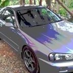
    • So I raised the car up a fair bit for shipping - see image - then lowered it again when it arrived. I then rushed to get an alignment in NL before the track and the shop just wasn’t anywhere near as precise as what I got in Japan. The guys that did the alignment this week said there was a fair amount of toe in the rear that could have contributed to the understeer. It was also the case that the rear camber went from about -2 to -3 at the shop in NL. However, since I’ve now got slightly wider tires in the rear - NS2Rs run wider than Accelera 651S - I could only get a minimum of -3 in the rear now due to clearance. Front is now -2.75 (-2.45 in minutes) due to being raised a bit (previously -3 in JP). So it’s likely a combination of the two factors, camber and toe. The issue now is I have more camber in the rear than the front and the next step on the front Cusco arms will put me at -3.5ish front which seems a bit excessive to me. The weird thing is I’ve never had any understeer at the track in Japan but they are very different circuits - Japanese circuits are much slower than the one I’ve been to here.    I’m probably going to have to start another thread for the E90. The plan is sort of to keep it as a daily but progressively mod it into a track car - honestly, you need a cage for the sort of speeds you go here. Just ordered the M3 front arms btw.  Love the car despite it being in pretty shitty condition. Oil analysis came back okay and it seems to have stopped consuming oil since fixing a load of engine bay things. Saw yours is a 335i right? f**king mistake on my part getting the DI N53 over the N52, fuel economy is insanely good though at 14-16 km/L.   Cheers, it’s great to see the benefits and pitfalls of different places. I’m contemplating going back to the U.K. around next year as the cost of living in the Netherlands is just ridiculous. GF is nagging me to settle and buy a house but I don’t know what LSD to buy. 
    • Have you seen the Milwaukee Train Horn? It's a beast! I stumbled upon it while browsing for upgrades. I'm thinking of adding it to my ride for some serious sound. Here's the link if you wanna check it out: https://bosshorn.com/products/milwaukee-train-horn. Anyway, thanks again for sharing your method.
    • Anybody home...? I used to moderate this part of SAU about 20 years ago... hard to beleive it's still around basically unchanged with all the old posts pinned at the top. Amazing to read all those posts again.  If anyone drops by, I'm still in Japan (Nishinomiya, between Osaka and Kobe).  Cheers 🙂
×
×
  • Create New...