Jump to content
SAU Community

Recommended Posts

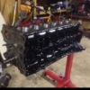
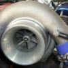
If You Guys Can Give Me A Rough Idea Of What This Should Make On A Rb25det

Mods Include

Gt35r .82 Exhaust Housing

High Mount Exhaust Manifold

Tial Wastegate

Forward Facing Inlet Xf Throttle Body

750cc Injectors

Tomei Poncams

Tomei Headgasket

Haltec Computer

Link to comment
https://www.sau.com.au/forums/topic/81859-what-sort-of-power-should-this-make/
Share on other sites

I know this isnt answering ya question but make sure u can use a XF tps with ya ecu. PowerFCs cant. I found out the hard way :D

i'll be trying to modify the standard tps somehow first.

if that can't be done i'll grab a haltec one and rig that up

If You Guys Can Give Me A Rough Idea Of What This Should Make On A Rb25det

Mods Include

Gt35r .82 Exhaust Housing

High Mount Exhaust Manifold

Tial Wastegate

Forward Facing Inlet Xf Throttle Body

750cc Injectors

Tomei Poncams

Tomei Headgasket

Haltec Computer

Have you got forgies to go with alll that stress

Some like to run leaner with less ignition timing and some richer with more ignition timing. But generally they end up making roughly the same power.

Personally I like the richer with more ignition timing method.

A tune should consist of fiddling with cam centerlines and combine that with the fuel and ignition setup. I could then see a 50rwkw difference.

Apart from that I doubt it would vary by anymore than 20rwkw or so by only tuning via the ign. and fuel maps.

That is providing the tuner isn't completely stupid and pulls shiet loads of ignition timing out.

This is dangerous in its self as less ignition timing = a higher EGT.

Exactly why I like the richer and more ignition timing. Lower EGT.

i was after more towards a HP rating as thats given by what wheels are used.

i dont think they run anything but a .7comp

well im pretty sure gcg quote them at 700hp

but people argue anwhere from 650-700 if thats what you were after

Create an account or sign in to comment

You need to be a member in order to leave a comment

Create an account

Sign up for a new account in our community. It's easy!

Register a new account

Sign in

Already have an account? Sign in here.

Sign In Now


  • Similar Content

  • Latest Posts

    • Um.... This is not easy. I will have a fiddle with it, but make no promises. I think, given the explicit resistances vs temperature, and your ECU measured voltages, it should be possible to match them up. I will do that by assuming a 5V supply from ECU to sensor, find out how much current would have to flow to produce that voltage, then use that current as a .... nah f**k. That won't work. The supply voltage is fixed, but there's nothing to say that the ECU regulates the current too. Um... I dunno. I guess there's a voltage divider setup in the ECU. As in, there's another resistance between the ECU's sense terminal and ground. That way, as the sensor resistance changes, that's how they get a floating voltage that varies with the temperature, without having to control the current. Give me a minute or 3.
    • *that* is a question for chatgpt (or someone that understands maths....but I'd try chatty). Drop them the table and ask for the formula
    • Alright. Exhaust has been looked at, and booked in 'soon'. I'm not 100% convinced it's going to be as good as possible but I'm going to go with it anyway. If I get a reasonable thing that works for 10 years I mean that's twice as long as I've lived with the current one. I have a more pressing issue. I have fixed my MPVI3 (by buying a new one). Excellently, one can wire in analog 0-5v inputs to the ECU itself. I had wideband already via Serial so I also wired it in via the direct input. The idea being I can use the standalone logging without a laptop and have Wideband data in it. The other wire I thought I'd use oil temp. This is where I've gone crazy. HPTuners requires you to implement a formula so you know how much volts = how much temp. This seems relatively simple to me. However I cannot find the scale for this anywhere on the internet, nor decipher how to figure it out without removing the sensor from the car. All I know is that voltage actually goes up as temperature goes down. I am using the actual gauge, so I can see what the temp is. The signal wire has been branched off into the MPVI3. EXAMPLE: 2.68v = 58C 2.7 = 57C 2.74v = 56C 2.8V = 54C 3.06V = 49C 3.18V = 47C 3.37V = 43C I think the gauge is 50-150C. It may be more. It may be less, because I can't find it for the love of f**k. It appears all the information about the gauges I have has been scoured from the internet, but the sender is VDO 320.021 I believe the resistance chart is this How the f**k do I convert this to a voltage? Once I have a voltage... I then have to perform this transform of said voltage to show it in the scanner: https://www.hptuners.com/help/VCM-Scanner/Content/vcm_scanner/defining_a_transform.htm @GTSBoy you're probably my only hope here TEST YOUR MIGHT
    • Here’s the updated and installed muse replica nismo ones … very happy with the outcome. Eventhough I painted my whole rear end due to my rich idle lol. 
    • Hmm. I had a good look (w/o searching, because I'm not logging in) and couldn't see it either. I distinctly recall the thread, not many weeks ago. It must have been removed or perhaps put into the back section. If it was in Off Topic you should at least have been able to search it up. So if I'm not hallucinating, it is fairly decently removed.
×
×
  • Create New...