
Garage Sale R33 Bits And Pieces
Announcements
-
Similar Content
-
-
Latest Posts
-
 Nice, thanks for sharing your progress....that's a pretty long list you are putting into it!
 -
 Decided to upgrade my pressurised plastic coolant expansion tank for a fancy pants alloy version The OEM versions can get brittle, even the new plastic one I got when I first got the car is a starting to show signs of "stress" I wasn't cheap, but it is basically unbreakable
 -

By pacman_1219 · Posted
Morning all, I have an RB25DET Neo that's in need of a rebuild. Will need new pistons etc due to detonation damage. Would anyone be able to recommend a shop in Southeast Queensland who I could bring my long motor to for a rebuild? Just want someone who knows RBs and whos built a bunch of them before. TLDR - recommended engine shops for RB rebuild. -
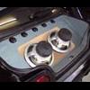
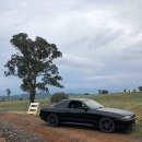
 Gday Thought it was about time I started a build thread! As expected this project has snowballed into a huge financial liability, but unless you’re strong willed and responsible, it’s not a surprise. Background - My first turbo car was an R32 GTS-4, got my full license and then totalled my Au Falcon a week later, so while trying to sell my RMZ450 dirtbike to buy another car a bloke offered to swap the R32 which at the time I felt like I was ripped off but looking back and seeing prices of those now ($40kish) it was a good deal, I didn’t know enough about these cars to appreciate what I had so sold it before the RB20 blew up. Between here and there, out of 12 cars I’ve owned the note worthy ones are a V8 Lexus SC400 (soarer), a couple of XR6 Turbos and my beloved S15 which I had for about 3 years, picked it up for $12500, repairable write off but she was fine, gun metal grey/pewter and bone stock/unmolested until I got my hands on it. Ended up spending about the value of the car and 280kw, 2 demerit points by the time I got defected and sold it for $14500 (also $40kish in today’s market, rip) Fast forward to the present day, I’m in a much better position financially and daily an MQ Triton (great cars, pipe down Ranger Bois), I cruised marketplace and car sales for a few months looking for another R32, the best deal I could find was an absolute rust bucket half finished project for $12000, until this R33 popped up in Port Macquarie for $18k - unregistered and barely running but decent shape, kept an eye on it for a few weeks and the price steadily dropped, $16k then $15k then $14k, that was the point where I was like shit someone’s gonna snatch this up! It was owned by a young bloke who had big plans but him and his missus just had a baby so smartest move financially for them but big gain for me. So 2 days later I’m towing a car trailer to pick this thing up. Roughly 2 weeks and $3500 later I’m cruising around Newcastle in my beat up R33 all smiles and dose noises! It only needed some basic shit to get it going, coil packs and air flow meter, electrical stuff and all fluids changed, 158k kms and running pretty good, nice smooth engine after oil and coolant flush - when I say coolant I mean it had been filled up with tap water, every gallery and heater element was filled with rust, 8-9 flushes later and still had brown liquid coming out but she’ll be right. The car was painted R34 Bayside Blue at some point but whether it was a cheap job or just not looked after is anyone’s guess, clear coat flaking like sausage roll. Was rethinking my choices and contemplating life, had it up for sale for $22k - still cheaper than any registered R33 but got little interest, next minute I had an opportunity at work - 6 months overseas for good money, so that was a no brainer, fast forward again and here we are with a 50% finished project. Current Mods - 200ish KW according to butt dyno Was tuned with Apexi PowerFC EBC (old school Greddy Profec) Stock turbo (more shaft play than a Tinder date gone right) 3inch turbo back Varex muffler Aftermarket injectors of mystery size, Power FC showed 36% duty cycle at full boost so not behd good size Someone had good intentions but stuck with the stock R33 MAF so we had misfires at 6000rpm due to the MAF hitting 5.2V So far I’ve redone the entire interior with carpet form Car Mats Direct, new Seats and steering wheel from Autotechnica, also sound system by Autobarn (mainly Kicker) Also MCA pro comfort coil overs - Hands down best purchase yet, worlds of improvement over the tired 30yrold shocks Goals - 450kw/600hp on flex tune New paint job - Midnight Purple 2 Engine is at the shop getting rebuilt with forged rods a pistons, new valves and springs, ATI Harmonic balancer, Aeroflow 7.5L sump, rear head drain and oil restrictors as per oil control thread* and cam covers modded for larger breathers, other stuff I can’t recall of the top of my head Parts purchased and to be installed once the engine is done - Engine loom from Wiring Specialties including these options: Haltech Nexus S3 R35 Coil pack conversion PRP Dual Trigger kit Fan controller Other Parts - 262 Kelford Cams Turbo - Hypergear ATR43SS3-ProS with T51R mod (whistly boi) 6 boost manifold (high mount) 50mm Turbosmart Pro gate (plumbed back for legal reasons) HKS Super Turbo Exhaust with High Flow Cat Custom 3.5inch dump and front pipe 1500cc Bosch injectors Fuel Pump walbro 525 Haltech MAP and IAT sensors Haltech Flex Sensor Fenix Radiator with dual thermo fans LS1 Alternator Kit Oil Filter Relocation from EFI solutions and Cooling pro oil cooler Many other things sitting in my garage waiting for that engine to come back. Progress pics to follow -
 -
 Losses have to be less with DC coupling. Provided the battery inverter has decent MPP tracking ability - which really shouldn't be a problem. It's not 2005 any more.
-


Recommended Posts
Create an account or sign in to comment
You need to be a member in order to leave a comment
Create an account
Sign up for a new account in our community. It's easy!
Register a new accountSign in
Already have an account? Sign in here.
Sign In Now