

GTRNUR
-
Posts
1,971 -
Joined
-
Last visited
-
Days Won
1 -
Feedback
100%
Content Type
Profiles
Forums
Events
Gallery
Media Demo
Store
Everything posted by GTRNUR
-
Good stories. I have a couple but I think the best one is actually something that a friend did when sharing with his asshole brother and girlfriend. He was a very non-confrontational kind of guy, very easy going. But he didn't take kindly to being psychologically tortured by his brother and girlfriend. You have to watch the quiet ones. Revenge is a dish best served cold. In his case this meant most of the food products in his brothers fridge had various secret flavours added that can only come from a penis.
-
 I have confirmed the rev limit soft cut was 7500 RPM. The two graphs on the dyno sheet were actually 4th gear 7500 rpm and 5th 6000 rpm pulls. The 5th gear run was an aborted run due to an intake hose blowing off. It stopped at 6000 RPM. Trent switched to 4th gear after the hose blew off for the third time, and did the 4th gear pull. The chart below is RPM vs KW and NM.
 -
That's the next engine you must be thinking about
-
It is either 7500 or 8000 now. I cant remember and haven't looked at the map since Trent re-tuned it.
-
Video at last! https://www.youtube.com/watch?v=7-07CnwwmF8
-
Perhaps down the track a little an EFR9180 with the 1.45 twin scroll will be the way to go to get more top end without sacrificing too much low end. This motor has achieved what I wanted it to do now though. The next two engines are where I'm going to pursue more power. The intercooler is a genuine Nismo core and is most likely not the restriction, however its had a lot of miles on it and has had some decent stone strikes. It will be replaced most likely with a hypertune core at some stage. The 6466 will go 550+kw easily if I up the MAP sensor to a 4 or 5 bar. The 525kw was far from being optimised. There was no point tuning it at the limit of the MAP sensor as the ability to detect an over boost situation no longer exists. The 30kw gain from just 2psi shows the engine is still waking up at this pressure level despite the top end drop off. For the moment I am very happy with the setup. I want to make the car look a little more pretty next, in case someone wants to photograph it.
-
No check valve, and no exhaust vacuum interaction. Pulls vacuum from the sump and head via a baffle system, to a ventrui on the intake between the turbo and filter. Any oil that enters the system returns to sump like a nismo setup, but at an elevated temperature to boil out any water vapor.
-
Joined the 500Kw+ club today with the V3 prototype of my engine. This was the power goal that I had hoped for, as it is designed to be a torque monster with the maximum possible low end performance. The tune is on E85 (75% content after the 98 octane tune), and was done in Cairns in 33 degree heat at 82% humidity. Open Deck Engines 3.4lt (3360cc) Block (Rb26 24U based block) Tomei Spec 2 head, Step 2 cams. Precision 6466CEA 1.0 Full Race manifold with twin tial gates. 4" turbo back, 90mm Trust TI-R titanium exhaust Greddy intake plenum Nismo Intercooler NPC twin plate Haltech with IO expander, doing fuel pump and auxillary cooling system control PWR 55mm twin pass radiator and custom oil-water heat exchanger, plus auxillary rear mount radiator and remote coolant pump. Ignition project plazma coils Completely enclosed crankcase breather system, designed to pull the engine into a vacuum under boost.
-
Update time! Today truely a great day. With the boost issue fixed Trent from Mercury Motorsport was able to get the engine to perform as I had hoped, and we finally got the 500KW ATW goal. We had a couple of minor issues with blowing off intercooler pipes again, but other than that the car performed flawlessly. Huge thanks to Trent @ Mercury Motorsports and Daniel Stephensen from LK motors for performing all the tuning and dyno setup. 526kw atw at 28psi (pipe blew off in this run). 495kw atw at 26psi 33 degrees, 82% Humidity! Stinking hot! I never saw hotter than 86 degrees on the MFD, (Oil and Water)! My cooling sytem rocks!
-
Under the parcel shelf you have a bunch of electronics, a rear strut tower brace and a battery. Then under the strut towers there is a fuel tank that straddles the diff. Below that is the rear cradle. What do you want to do with the tether point? Are you trying to setup an anti-theft tie down point?
-
Federal Tyres Splitting!
GTRNUR replied to grygtr's topic in Suspension, braking, tyres and drivetrain
Bit of a thread bump but this was my experience with the 595 Rsr's. Initially I was happy with the grip and that my understeer issue disappeared but... now. Front tyres have eggs and don't roll in a straight line. Left rear shows the tread having ripped away from the tyre, showing the steel belt inside. The belt has torn and there is nasty spikes of metal poking out. It has started to crack around the outside as well. The seam/overlap join is visible on all tyres. Not exactly confidence building given that the tread is peeling away too. My suspension guy says this is pretty common with federals and has seen it a bit recently in motorsport. But these tyres would have only seen over 200km/h on the dyno and have never had track time. They have about 8000km on them. The mould air-release hairs are still on all the tyres. The rest of the time I am mostly stuck in 80km/h traffic with the occasional burst of acceleration. Hope to swap these for some 4wd tyres instead from the local Federal dealer, and then off-load them to someone else. Switching to Nitto's for the GTR. -
I am still waiting on pistons for the next two engines. It took quite some time to get the specifications sorted out for something that will handle extreme punishment for an extended time. In the end I went with a custom JE and Trend DLC coated gudgeons. I'm told they will handle 1800hp+, with a specification normally found in a methanol engine. I completed the rear R35 GTR brake conversion, and have a functional hand brake thanks to modified Toyota Rav 4 hand brake shoes. Other than that I have been working on the front suspension lately. I've changed the lower control arms to R33 GTR items, so I can use adjustable tension rods. I've yet to locate or make a set of roll centre correction spacers. Upper arms will be fitted with superpro offset bushes to correct camber. I've also done the first plug change and compression test since the tune. Dry test and every cylinder is within 3psi, which is amazing. The best leak down and pressure test result I've ever had. Then I re-pressure tested the entire intake side of the engine and found the reason I didn't break 500kw in the last tune session. At some stage between the first and second tune sessions, a weld had developed a small crack in a pipe that links the turbo to the intercooler. So essentially I made 610hp with a serious induction leak. I've had to turn off boost control now too, as it hit boost cut on the first drive once the leaks were fixed. I believe the leak was in part due to a mostly torn through nismo engine mount, as there has been other signs the engine has moved a little too much. I was blowing off pipes during dyno tuning, but also, the plenum has made contact with the clutch master cylinder at some stage. I changed my first front inner CV boot too. What a fun task that is. That's all for now.
-
Update. I've had some time to get stuck into the car again lately. I put in the R33 GTR lower control arms and hard race castor rods. Also had to replace a LH inner CV boot which I took care of yesterday. Just waiting on camber bushes so I can replace the outer upper control arm bushes with superpro bushes and an eccentric offset pin. I suspect I'll have to look at getting some roll centre adjusters as well, and possibly some different tie rod ends to eliminate bump steer.
-
Gtr35 Brembos Kits To Suit Gtr32 & 33
GTRNUR replied to zoom's topic in For Sale (Private Car Parts and Accessories)
I did as Chris suggested. Used and R32/R33 Endless calliper adapter kit drilled and tapped, and mounted DBA 5000 380mm rotors front and rear. The braking is incredible. Matches the R34 master cylinder, no changes necessary. This is an essential upgrade for any 400kw+ GTR. -
I'd put money on the bore size being too big for your pistons. I've never seen a set of CP rings that didn't need filing to get the gap right. You will probably find you have 12-16 thou at least, not 4.
-
Test For Coolant System Additives To Stop Leaks
GTRNUR replied to Nismo 3.2ish's topic in General Maintenance
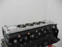
Depends on how hot your oil was getting on long drives, how long you drove it for, and how fast the leak was. Your catch can would have told a differnet story, unless it returns to sump. Oil thats up to temp (85+) will boil off the water in coolant for a slow leak, yet also slowly contaminate it. The water would collect at the very bottom of the sump too, under 8lt of oil. Not detectable on a stick. I'd like to see a photo of the top of the block where the 1/2" thread inserts were installed for the head studs when you have it apart. -
I disagree with burnign HHO gas as being "pretty much the same thing as burning hydrogen in air". There is a MASSIVE difference between burning hydrogen in air and burning the perfect 2 * H2 + O2 mix. An example is an experiment that was performed back in Yr12 chemistry. A steel can measuring about 80cm in diameter and 200 tall had a small hole with a nail made in the bottom, which was then covered with tape. The can was then filled with pure hydrogen by means of disolving aluminium foil in hydrochloric acid in a conical flask with a hose attached. Bulk quantities of H2 gas are made. The can is filled with water, which is then displaced with the hydrogen. Next the can is held with the hole taped end upright, and placed on the floor on a steel mesh. The tape is removed, and the hydrogen gas lit. The hydrogen burns steadily with the amount of ferocity you would expect from a candle burning parafin wax. As the gas rises in the can and burns out the top, air containing O2 is drawn into the bottom. The flame slowly burns lower and lower. As it is about to disappear, a whistling sound can be heard. Then when you think the flame has gone out, BOOM! The can is launched from the floor to over 2.7M in the air, leaving a half moon shaped dent in the plaster ceiling. So from this example we have controled combustion of Hydrogen, vs combustion of hydrogen and oxygen when the mixtures are correct to produce a complete burn instantly. (I had a cool science teacher)
-
I'm not sure if any of you have noticed, but making HH0 gas via electrolysis is a LOT different to what Hyundai are doing with pure Hydrogen in REAL fuel cells. The Hydrogen electric fuel cells produce electricity and drive an electric motor. There is no internal combustion occurring anywhere. Storing Hydrogen at very high pressure has a degree of explosive risk associated with it, but no where near as much as storing HH0 gas would be. While a ruptured high pressure hydrogen gas cylinder would spew hydrogen liquid and gas out rapidly and nearly instantly, if ignited it would burn much like normal gasoline. The rate of the burn being contained by the available amount of oxygen in the environment. A good example would be the Hindenburg photos that everyone has seen. Granted a huge power fireball, but still a slow burn. It didn't scatter the air ship over a 10km radius. Not so with HH0 gas. The perfect mix would allow for instant combustion of the entire fuel container contents. More explosive than any actual explosive you could care to mention short of nuclear. This is why stored HHO gas will never go anywhere in the automotive world. Once they do master storage of Hydrogen in pressure containers that are incapable o being punctured, which would otherwise result in a massive gas discharge, the door MAY be opened to allow fitment of hydrogen fuel tanks to internal combustion engine equipped cars. Regarding keeping combustion temps under control to reduce emissions, water injection is the answer to that. It would work well with forced induction too, because you still need to compress air to get enough oxygen for the burn, but no intercooler would be required if you were to inject raw Hydrogen into the cylinders.
-
Used pair of R35 GTR Alcon 390mm rotors + hats Just machined, 35.41 and 34.7mm thickness. Ready to install. Located in Cairns, QLD. $1500 + $75 postage for most places in Australia. Ph/txt: 0434 147 478 or message me.
-
Yes thanks, I figured they just drilled them a little different. From all the pictures I've seen it is the same casting. Ironic that the nismo upgrade part for the BNR34 is to switch back to what is basically the BNR33 part...
-
So it only took 4 days or research but I have found the answer in the form of a Nismo upgrade part that is both R33 and R34 GTR compatible. http://www.rhdjapan.com/nismo-circuit-link-set-skyline-bcnr33-bnr34-wgnc34.html $330 for a left or right side box setup of R33 GTR control arms that have a little more welding done on them, then painted silver and a Nismo sticker is added. From RHD Japan: The NISMO Circuit Link Set Skyline BCNR33 BNR34 WGNC34 includes the front upper link and the front transverse link. Circuit Link Sets are sold separately as a left side set or a right side set. The items are more rigid than the OEM units and are a great upgrade when fine tuning the suspension of your vehicle. The Circuit Link Set proves to be most useful when used for circuit racing to improve cornering and reduce the understeering characteristics of your vehicle. This is done by the change in suspension geometry (high caster and negative camber). Please remember that these sets are sold separately by sides. If a full set is needed please add two (2) to your shopping cart and specify. If only a certain side is needed, please add one (1) to your shopping cart and specify which side. For a quick overview, please click View All Pictures, see the bottom images. This item is numbered 1 on the first picture, the Skyline GT-R R33. Please Note, this part may be numbered differently on your model, please refer to pictures. Nismo is the best for anything Nissan and is the top choice of all major Nissan tuners out there! Upon purchasing please state the car from the compatibility list that you would like to have the NISMO Circuit Link Set for. Get this and all your JDM at RHDJapan!! So my solution is going to be to get 2 R33 GTR Control arms, 2 x Hardrace R33 Caster rods, and adjustable upper control arms. All with rubber bushes so it will be a nice and streetable setup with a high degree of adjustment. The addition of roll center spacer adjusters will complete the setup. Complete setup is costing $600.
-
R34 lower control arm. R33 Lower control arm (minus caster rod)
-
No the lower front control arm on the R34's are a cast alloy item and are not adjustable. The R33 arms are a 2 piece part, with a control arm that anchors the hub to the K-frame, and has a tension/castor adjustment rod. I just don't want to be the first to attempt this.. so I'm looking for some info from someone that has already done it. It seems that the Nismo Circuit Link system uses what appears to be an R33 control arm, but I cant find any information to confirm if the part is the same. http://www.nismo.co.jp/en/products/competition/lb/pdf/bnr34_1.pdf
-
Im looking for a bettter option to obtain more accurate caster adjustment than using offset bushes in the alloy front lower control arms on an R34 GTR. Has anyone tried fitting an R33 GTR lower control arm, with an adjustable castor/tension rod to an R34? It seems the only other option is using Ikeya arms which are not only expensive but also clearly a modificaiton that will attract police attention if the car is ever inspected.
-
My bad... that's not 1Kw. I meant 1Mw.

