Jump to content
SAU Community

Recommended Posts

alright let's get this discussion underway.

ITB throttle bodies + custom adapter plate + custom trumpets.

pros?

- increased power

- increased response

- the sound!

- watching the butterflies open and close :D

cons?

- cost. i have no idea, but judging by the costs of rb26 throttle bodies, and the cost of relocating a few things, custom bits and pieces (1-1.5k ??).

- r&d required for tuned length intake runners (adjustable runners?) narrow power band.

some other things to bring up:

- cheaper to use RB26 throttles or buy some pre-fabricated ones?

- legalities?

- adapt small pod filters onto the end of each.

- anyone who is (knows of someone) who is cluey with ITBs? mainly hondas, mini, porsche, and old school nissan owners with some know how.

R.I.P.S in new zealand makes adaptors for rb26 throttle bodys to rb25 heads. if rb26 ones are hard to find use some 4age throttles. sure you will need 2 sets but they will still work but thats alot more custom parts though... they make small air filters to fit on ITBs

you would be lucky to find a direct fit kit as nobody really makes performance parts for NA skylines. i havnt even seen an after market intake pipe...

It's not the first question? Or it's not in a 33? :huh:

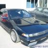
the later, its an R32 - the headlight and grill are a dead giveaway.

R.I.P.S in new zealand makes adaptors for rb26 throttle bodys to rb25 heads.

you would be lucky to find a direct fit kit as nobody really makes performance parts for NA skylines. i havnt even seen an after market intake pipe...

agree. worked NA skylines is hardly widespread in japan let alone anywhere else.

any idea on the cost of these adaptors Geoff? might be a cheap alternative to using an RB26 head.

if you were going to do this you'd need to go all out.

forged high comp pistons, lighter rods, balanced bottom end with around 11.5:1 Comp ratio, some nice meaty cams, maybe 288's or something around that with a shortish duriation but high lift. basically want to make the bottom end hold together and swing to around 10,000 rpm.

defo use a plate and use the RB26 ITB's, make some nice and long intake trumpets, big air box feeding air direct to all of them.

and then put it in something light...

those of you who frequent these formus will remember not to long ago i did a write up on my car well i've changed direction and kept it rb25 and gone hi compression.

looking at anywhere from 11.5:1 to 12:1. did alot of work to the head including lifting all the buckets getting all the valves reseated and 5 angel cut ( takes a long time is expensive but its the best!!) new valve springs and of course a port and polish. getting the intake polished and the manifold double split. getting the whole lot balenced before she goes back on to. slotted in new fuel rail to support 440 injectors. big cams, cam gears blah blah blah.

forgotten a few things im sure but you get the idea. After many weeks and many long hours i get her back this week and put it back on this weekend. so if anyone is after figures i'll have them next week after she goes to the tune shop.

as for ITB's i did alot of research on cost gains everything and they just not worth it. the gains you get can be gotten elsewhere for much cheaper and its nothing you can't tune around if you have a good computer and a tuner who knows what their doing. that being said the sound and look is unbeatable.

Do not use mini pod filters or socks to filter your throttles.....this completey wrecks the point of having a trumpet on there as it create far to much disturbance in the air flow as it try to pass over the trumpets completey wrecking there use.

There is a certin filter used by club cars and bikes which was invented in UK and are now made in Australia also. It other full filtering but with zero restiction.

When i had my hachi i spoke to a guy in UK who builds race engine which have quad throttle bodies and he has had gains of up to 30hp by just pulling off the sock filters and using these special made items along with a good setup.

I would make a base plate that sat on the lip that rolls back over the outside of the trumpet so it has more volume area to suck from and have one big single filter over the whole set of throttles making sure you give atleast 2cm of gap from filter to the ends of each trumpet. The filter is not like ur pod filter type it more like a long bubble looking filter thats made of 3 different filter materials.

If you need more info about these special filters that other full flow and zero restriction hit me PM and i can try to find his email address.

But when it comes to NA you want to try and get every extra HP you can and use your main source of air flow to its max potential.

- Luke

the later, its an R32 - the headlight and grill are a dead giveaway.

agree. worked NA skylines is hardly widespread in japan let alone anywhere else.

any idea on the cost of these adaptors Geoff? might be a cheap alternative to using an RB26 head.

um from memory it was about $500 witch to me seemed expencive.. but then it means it would fit well.

a super high powerd na car would be almost undrivable on the street i recken.

im aiming for about 150kw witch i have reciently found out is quite easily achievable with my rb30de.

Create an account or sign in to comment

You need to be a member in order to leave a comment

Create an account

Sign up for a new account in our community. It's easy!

Register a new account

Sign in

Already have an account? Sign in here.

Sign In Now


  • Similar Content

  • Latest Posts

    • Nah, that is hella wrong. If I do a simple linear between 150°C (0.407v) and 50°C (2.98v) I get the formula Temperature = -38.8651*voltage + 165.8181 It is perfectly correct at 50 and 150, but it is as much as 20° out in the region of 110°C, because the actual data is significantly non-linear there. It is no more than 4° out down at the lowest temperatures, but is is seriously shit almost everywhere. I cannot believe that the instruction is to do a 2 point linear fit. I would say the method I used previously would have to be better.
    • When I said "wiring diagram", I meant the car's wiring diagram. You need to understand how and when 12V appears on certain wires/terminals, when 0V is allowed to appear on certain wires/terminals (which is the difference between supply side switching, and earth side switching), for the way that the car is supposed to work without the immobiliser. Then you start looking for those voltages in the appropriate places at the appropriate times (ie, relay terminals, ECU terminals, fuel pump terminals, at different ignition switch positions, and at times such as "immediately after switching to ON" and "say, 5-10s after switching to ON". You will find that you are not getting what you need when and where you need it, and because you understand what you need and when, from working through the wiring diagram, you can then likely work out why you're not getting it. And that will lead you to the mess that has been made of the associated wires around the immobiliser. But seriously, there is no way that we will be able to find or lead you to the fault from here. You will have to do it at the car, because it will be something f**ked up, and there are a near infinite number of ways for it to be f**ked up. The wiring diagram will give you wire colours and pin numbers and so you can do continuity testing and voltage/time probing and start to work out what is right and what is wrong. I can only close my eyes and imagine a rat's nest of wiring under the dash. You can actually see and touch it.
    • So I found this: https://www.efihardware.com/temperature-sensor-voltage-calculator I didn't know what the pullup resistor is. So I thought if I used my table of known values I could estimate it by putting a value into the pullup resistor, and this should line up with the voltages I had measured. Eventually I got this table out of it by using 210ohms as the pullup resistor. 180C 0.232V - Predicted 175C 0.254V - Predicted 170C 0.278V - Predicted 165C 0.305V - Predicted 160C 0.336V - Predicted 155C 0.369V - Predicted 150C 0.407V - Predicted 145C 0.448V - Predicted 140C 0.494V - Predicted 135C 0.545V - Predicted 130C 0.603V - Predicted 125C 0.668V - Predicted 120C 0.740V - Predicted 115C 0.817V - Predicted 110C 0.914V - Predicted 105C 1.023V - Predicted 100C 1.15V 90C 1.42V - Predicted 85C 1.59V 80C 1.74V 75C 1.94V 70C 2.10V 65C 2.33V 60C 2.56V 58C 2.68V 57C 2.70V 56C 2.74V 55C 2.78V 54C 2.80V 50C 2.98V 49C 3.06V 47C 3.18V 45C 3.23V 43C 3.36V 40C 3.51V 37C 3.67V 35C 3.75V 30C 4.00V As before, the formula in HPTuners is here: https://www.hptuners.com/documentation/files/VCM-Scanner/Content/vcm_scanner/defining_a_transform.htm?Highlight=defining a transform Specifically: In my case I used 50C and 150C, given the sensor is supposedly for that. Input 1 = 2.98V Output 1 = 50C Input 2 = 0.407V Output 2 = 150C (0.407-2.98) / (150-50) -2.573/100 = -0.02573 2.98/-0.02573 + 47.045 = 50 So the corresponding formula should be: (Input / -0.02573) + 47.045 = Output.   If someone can confirm my math it'd be great. Supposedly you can pick any two pairs of the data to make this formula.
    • Well this shows me the fuel pump relay is inside the base of the drivers A Pillar, and goes into the main power wire, and it connects to the ignition. The alarm is.... in the base of the drivers A Pillar. The issue is that I'm not getting 12v to the pump at ignition which tells me that relay isn't being triggered. AVS told me the immobiliser should be open until the ignition is active. So once ignition is active, the immobiliser relay should be telling that fuel pump relay to close which completes the circuit. But I'm not getting voltage at the relay in the rear triggered by the ECU, which leaves me back at the same assumption that that relay was never connected into the immobiliser. This is what I'm trying to verify, that my assumption is the most likely scenario and I'll go back to the alarm tech yet again that he needs to fix his work.      Here is the alarms wiring diagram, so my assumption is IM3A, IM3B, or both, aren't connected or improper. But this is all sealed up, with black wiring, and loomed  
×
×
  • Create New...