
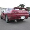
Heaps Of R33 Parts And Accessories

Announcements
-
Similar Content
-
-
Latest Posts
-
 Bummer...yeah i "need" something to "ease" up the work and for my driving it would be enough. Iam counting the tune "without" turbo. I do not mean "cheap" like something from Temu around 200 USD, "Cheap" is something around 1000 USD?
 -
 Starter motors used to use the weight of metal (magnets) to provide torque. Now they use (more) current instead. This. It's completely normal.
 -
 So thing that had me stumped, but I think is OK....is that when it was up in the air, in neutral I had it running to bleed to coolant while I put the wheels back on. I noticed the rears were turning (slowly) which I'd never seen before 20250928_163512.mp4 Because there had been an issue with clutch slip due to pedal adjustment on the dyno, I assumed there was still and issue so spent some quality time upside down under the dash adjusting the pedal....but no matter what I did the wheels still turned in neutral. Even disconnected the master cylinder to pedal rod and same. In despair, I even removed the clutch slave so there was no chance of any preload causing it.....still happened. So either: 1. Something is not right in the bellhousing, or 2. Its a thing sometimes with cold, thick gearbox oil Internet says it might be 2, I hope so!
 -
OK, few more things sorted and it is ready for a shakedown on 10-Oct, with one weird thing. Changed the run in oil and filter for the good stuff. 8l came out, about 8.5 went in with filter so that looks all good. Changed the starter (again), this time for a brand new one, works good. Interesting that the Taaaarks one is shorter than factory but spins harder, I guess electronics have moved on a little in the last 30 years. Will be nice to have a bit of extra space under there. Put the timing cover back on, and noted where the cam gears were set as a record. Will need to double check the timing but it is pretty close. Also put the coil pack cover and intake snorkel back on. Exhaust Inlet Changed the water out for coolant, bled up nicely. Removed the rear brake pads (well worn factory sumitomo ones!), gave the hardware a good clean and reassembled. I've put bendix XP on the back again because the price is excellent at $150 a set and they worked well on the V37. Front pads have plenty so no issue there
-

-


Recommended Posts
Create an account or sign in to comment
You need to be a member in order to leave a comment
Create an account
Sign up for a new account in our community. It's easy!
Register a new accountSign in
Already have an account? Sign in here.
Sign In Now