Jump to content
SAU Community

Recommended Posts

What happened to that cranky modified R34 N1 NUR engine you had built for your car? Ive seen the build pics of the headbeing ported and modified in japan at prime garage from memory.. on the here forum somewhere. Why arent you driving the car already!

Cause the beer man is a pansy now lol :D

  • Replies 378
  • Created
  • Last Reply

Top Posters In This Topic

Top Posters In This Topic

Posted Images

Congratulations Ian!

This is Aussie engineering and ingenuity at its best. Well done!

I will surely be interested when the engine kit is commercially available!

Matt

Thanks Matt. Planning the next engine upgrade already?

It was in part Racepace Ben's work on his version of an RB29 open deck engine that inspired me to undertake this project. Any kit I might end up hoping to sell is still at least 12 month off off. I need to prove my design and find the money to do a small production run. As you might imagine, funding this little project hasnt exactly been cheap.

Nothing in performance engineering ever is....But its worth it! Great to hear the tear down looked good.

Cant wait to see the results!

Nice engine! Congrats'.

How do you cool down your spacer plate area? Is the space between plate and sleeves filled with coolant?

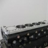
Best explained with a picture... The sleeves have coolant all the way around them at the top (where the most combustion heat occurs, 1" from the top of the cylinder).

post-a278649-DSC01932.JPG

In theory the open deck sleeved block will run cooler than a normal closed deck, as the hottest part of the cylinder is exposed to coolant. Closed deck blocks have less cooling surface area around the top of the cylinder and as a result conduct more heat to the block.

Sealing in combustion gases properly does not require a large surface area, or "more meat" as you put it. In fact the opposite is true. The less surface area there is, the better the seal will actually be for any given clamping pressure.

Imagine a motor that has 1 ton of clamping pressure holding the cylinder head down and compressing the head gasket. This force is applied by the head studs in order to compress the head gasket so it seals combusion chambers, and isolates water and oil galleries. Whether that be an open or closed deck engine, that 1 ton of pressure is spread evenly across the sealing surface of the top of the block.

So, if the engine is a closed deck type block there is more surface area than there is with an open deck block. So for the same head clamping pressure, the open deck engine will actually seal better.

But really its not that simple. The sleeves are not machined to be the same height as the spacer plate like you might think. When machining I take into consideration material expansion due to temperature change for the sleeves, spacer plate, and the aluminium gasket that seals the spacer plate to the block. As the motor heats up, the pressures across the head gasket actually changes in an open deck engine, but the head gasket has to seal across the engines entire operating temperature range.

Hope that makes sense.

Edited by GTRNUR

Oil returns were drilled and are a little larger in this build. I didnt bother with an external return. The restrictor combined with the 8lt oil capacity should be more than adequite for a street engine.

Oil returns were drilled and are a little larger in this build. I didnt bother with an external return. The restrictor combined with the 8lt oil capacity should be more than adequite for a street engine.

mate you impress me more and more with every post.

well done :)

Next job for you is to make the cylinder sleeves integral with the head, and use oil pressure or cam to lift the head off the block a couple of thou with revs and boost. Run 11:1 off boost and as revs/boost increases drop it down to 7.5:1 :) You can do it, easy! :(

This engine is almost as cool as your Bug :(

Thanks for the kinds words guys. It means a lot to me that I've captured the attention of guys like you too Paul considering your expertise and some of the cars that you build and work on.

Roy, I don't know about varying the combustion chamber size, but I have a few idea's on how to implement a constantly variable intake and exhaust cam system. Somthing I might toy with on the next engine I think.

Update!

I received the lab results back from Hastings Deering today. The oil sample results came back with a water content result of less than 0.1 PPM(parts per million), which means my sleeves and spacer plate are sealing perfectly. Pressure testing was performed at room temperature up to 100 degrees coolant temperature with 35PSI in the cooling system.

The next step which is installing the engine in the car will hopefully happen in 3-4 weeks. I still have to source a couple of rare parts in order to complete the engine, and I want to replace the cheapie silicon hose kit that Ive used temporarily under the intake plenum with something better.

Thats all for now.

Ian

Sealing in combustion gases properly does not require a large surface area, or "more meat" as you put it. In fact the opposite is true. The less surface area there is, the better the seal will actually be for any given clamping pressure.

Imagine a motor that has 1 ton of clamping pressure holding the cylinder head down and compressing the head gasket. This force is applied by the head studs in order to compress the head gasket so it seals combusion chambers, and isolates water and oil galleries. Whether that be an open or closed deck engine, that 1 ton of pressure is spread evenly across the sealing surface of the top of the block.

So, if the engine is a closed deck type block there is more surface area than there is with an open deck block. So for the same head clamping pressure, the open deck engine will actually seal better.

But really its not that simple. The sleeves are not machined to be the same height as the spacer plate like you might think. When machining I take into consideration material expansion due to temperature change for the sleeves, spacer plate, and the aluminium gasket that seals the spacer plate to the block. As the motor heats up, the pressures across the head gasket actually changes in an open deck engine, but the head gasket has to seal across the engines entire operating temperature range.

Hope that makes sense.

Well you have me convinced that you know what you are doing...

All I have to do now is win lotto and get you to build me one lol

Well you have me convinced that you know what you are doing...

All I have to do now is win lotto and get you to build me one lol

Its taken nearly 12 months or R&D to get the engine designed and built to this stage. While I'm not an engineer I have had engineering support from one of the most skilled firms in the country. They have done it all from aerospace R&D to medical/surgery equipment design and manufacture. I have been very fortunate to have been able to use their knowledge to make this project happen.

The engines if and when they go into production arent going to be as expensive as you might well imagine. 2.9-3lt can be made very easily and reasonably cheaply from mostly common available components(which is the key point of the design). The expense in the 3.1 and 3.2lt versions is due to the need for pauter I-beam rods(which are also longer), because at 90 degrees BTDC and ATDC the side of the rod gets very close to the bottom of the sleeve. H-beams just will not clear. The 3.1 bottom end should be about 1/2 the price of an OS giken engine though and support about 1000HP should you configure a head/turbo in drag tune.

what is the thickness of your spacer plate? looks to me its 20mm?

btw nice work :(

Thanks! It measures about 20mm including the alloy spacer plate gasket.

by half the price of an OS Giken engine do you mean ~$15,000?

Yeah about that if pauter rods are used. So not much different to the price of a strong RB30 based bottom end.

I'd rather not speculate too much on pricing yet though. I've yet to thouraghly prove the first engine, install it in a car and produce some numbers with it (km's and kw's etc).

  • 1 month later...

Yes it has been a while... Ive been sucked into some other projects but the RB31 has not come to a complete stand still.

Things have been on hold for about a month while getting a little more machining done on a new spacer plate that I have had to make. I had sent the engine south to have it run up and tested on an engine dyno and only got it back 3 weeks ago. Testing revealed an issue with how my spacer plate sealed against the nitto head gasket. After a few dyno runs and I had another oil test done and a little water in the oil.

The leak turned out to be from the coolant chamber (around the sleeves), and went in between the layers of the multi-layer gasket and into an oil return hole. It was a small leak as only trace amounts of water were found. It didnt present as an issue until the engine was heat cycled under load a few times with the cooling system pressuised to a high pressure.

Metal shim gaskets can only tolerate about 2-3 thou of surface variation, and the temperature differences is what caused the gasket to begin to leak. It was caught in time though and before damage was done. Ironically it would have worked perfectly if I had used a factory head gasket (or a copper one), as they will tolerate much more surface variation and being a solid gasket they wouldnt have leaked. The updated spacer plate fixes the issue though. I hope to have the remaining parts that I need to put it back together again in about 6-8 weeks. Realistically though this also means 3-4 months till it is installed in my car.

Testing did reveal some interesting results which have promoted me to have the head clearanced for bigger cams. I will still be starting in car testing with standard cams but the engine will greatly benefit from the flow increase of some large lift 264 degree procams. I still want it to idle and run like a stock engine though, so the larger cams will only go in if I decide to go chasing more power than 450kw. Power isnt the goal of the project though... and I have to keep reminding myself about that...

I am planing to use a slightly larger crank as wellto bring the displacement up to fraction short of 3.2lt. This will max out the potential for this block/sleeve setup and is the largest rotational setup that will fit the block. The main reason for this is that I want maximum turbo response. My plan back when I had started on this project had been to use 2860-5's on the 3.1lt, but the HKS GTRS's that I ended up with were sourced for a price I couldnt pass up.

Thats about all for now.

Create an account or sign in to comment

You need to be a member in order to leave a comment

Create an account

Sign up for a new account in our community. It's easy!

Register a new account

Sign in

Already have an account? Sign in here.

Sign In Now


  • Similar Content

  • Latest Posts

    • @Haggerty you still haven't answered my question.  Many things you are saying do not make sense for someone who can tune, yet I would not expect someone who cannot tune to be playing with the things in the ECU that you are.  This process would be a lot quicker to figure out if we can remove user error from the equation. 
    • If as it's stalling, the fuel pressure rises, it's saying there's less vacuum in the intake manifold. This is pretty typical of an engine that is slowing down.   While typically is agree it sounds fuel related, it really sounds fuel/air mixture related. Since the whole system has been refurbished, including injectors, pump, etc, it's likely we've altered how well the system is delivering fuel. If someone before you has messed with the IACV because it needed fiddling with as the fuel system was dieing out, we need to readjust it back. Getting things back to factory spec everywhere, is what's going to help the entire system. So if it idles at 400rpm with no IACV, that needs raising. Getting factory air flow back to normal will help us get everything back in spec, and likely help chase down any other issues. Back on IACV, if the base idle (no IACV plugged in) is too far out, it's a lot harder for the ECU to control idle. The IACV duty cycle causes non linear variations in reality. When I've tuned the idle valves in the past, you need to keep it in a relatively narrow window on aftermarket ecus to stop them doing wild dances. It also means if your base idle is too low, the valve needs to open too much, and then the smallest % change ends up being a huge variation.
    • I guess one thing that might be wrong is the manifold pressure.  It is a constant -5.9 and never moves even under 100% throttle and load.  I would expect it to atleast go to 0 correct?  It's doing this with the OEM MAP as well as the ECU vacuum sensor. When trying to tune the base map under load the crosshairs only climb vertically with RPM, but always in the -5.9 column.
    • AHHHH gotchaa, I'll do that once I am home again. I tried doing the harness with the multimeter but it seems the car needed a jump, there was no power when it was in the "ON" position. Not sure if I should use car battery jump starter or if its because the stuff that has been disconnect the car just does send power.
    • As far as I can tell I have everything properly set in the Haltech software for engine size, injector data, all sensors seem to be reporting proper numbers.  If I change any injector details it doesnt run right.    Changing the base map is having the biggest change in response, im not sure how people are saying it doesnt really matter.  I'm guessing under normal conditions the ECU is able to self adjust and keep everything smooth.   Right now my best performance is happening by lowering the base map just enough to where the ECU us doing short term cut of about 45% to reach the target Lambda of 14.7.  That way when I start putting load on it still has high enough fuel map to not be so lean.  After 2500 rpm I raised the base map to what would be really rich at no load, but still helps with the lean spots on load.  I figure I don't have much reason to be above 2500rpm with no load.  When watching other videos it seems their target is reached much faster than mine.  Mine takes forever to adjust and reach the target. My next few days will be spent making sure timing is good, it was running fine before doing the ECU and DBW swap, but want to verify.  I'll also probably swap in the new injectors I bought as well as a walbro 255 pump.  
×
×
  • Create New...