Jump to content
SAU Community

Recommended Posts

hey Steve,

any issues with temps after the grout fill job?

Yo,

motor just got stripped down and reported on.....

Engine temps and water temps were fantastic whilst on track

max of ~90 degrees after each session (air guides/twin thermos air/breather tank were fabricated)

draw back.... concrete caused a hairline fracture upon setting (still tracked for 6 events after) :)

all parts in great condition, would reuse consumables if a street car but not taking any risks with new N1 block

:cheers:

Fire wall bars are cut that accuratly we can weld the tube back to the fire wall to seal it up, no cut plates required....

post-20349-0-65316300-1357544993_thumb.jpg

And on the inside shit just got wild

post-20349-0-85504400-1357544972_thumb.jpg

post-20349-0-29056800-1357544984_thumb.jpg

post-20349-0-70476700-1357545005_thumb.jpg

Hopefully finish off the front end of the cage tomorrow, few more bars to through to the strut towers and more chassis reinforcement to come.

First stage of this monster cage is now done.

Basicly there are plates welded to the area of the floor where the chassis rails are spot welded to the fire wall. The tubes running to those plates actually go through the plate and are welded to the inside of the actual chassis rail. The plate is then welded ontop to reinforce the rail to both the cage and the fire wall.

There is obviously tirangulation to those critical pick up points.

There is 3 bars running out to 3 points on the strut towers.

One horozontally out which will oppose the side intrusion. One out to the strut top and tower intersection which is X'ed inside the car and another from the base of the front leg to the side of the tower where the camber arms are bolted to.

The bar at the base of the front leg to the chassis rail bars is there for two reasons, one is to aid in a side impact, transfering the force to yet another strong point of the chassis and also to provide a triangulated support for the main rail support bar.

enough explaining, enjoy the first stage of what is probably the most comprehensive cage anyones ever put into a skyline.....

post-20349-0-28354700-1357631393_thumb.jpg

post-20349-0-07192500-1357631402_thumb.jpg

post-20349-0-77773200-1357631407_thumb.jpg

post-20349-0-73332000-1357631412_thumb.jpg

post-20349-0-54860100-1357631416_thumb.jpg

post-20349-0-83838700-1357631419_thumb.jpg

post-20349-0-05931000-1357631423_thumb.jpg

Steve mentioned people were asking him how the car was going.

Update, the cage is nearing completion, hopefully tomorrow the hoop will have its diagonals and the front bases plated up.

Fab work left is some new jacking points under the car, pedal box frame and install, seat mounting and a new steering coloum.

Then a rewire before being sent off for paint

post-20349-0-03858500-1358231799_thumb.jpg

post-20349-0-79559900-1358231800_thumb.jpg

Back to the top for this one,

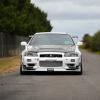
Its getting a face lift

post-20349-0-46256700-1357378574_thumb.jpg

post-20349-0-98805600-1357378575_thumb.jpg

When someone drops a car like this off at pro fabrication and says I dunno what I want just make it good the wheels start to turn.

Ive designed and FEA tessted the following cage and thats whats going into this R34

Front section to strut towers

post-20349-0-70588500-1357379010_thumb.jpg

post-20349-0-66834800-1357379012_thumb.jpg

post-20349-0-91640400-1357379015_thumb.jpg

post-20349-0-39359800-1357379019_thumb.jpg

post-20349-0-76991800-1357379021_thumb.jpg

post-20349-0-39872700-1357379024_thumb.jpg

post-20349-0-45767600-1357379026_thumb.jpg

When you say 'FEA tested' what exactly have you done. I'm assuming a beam model of the cage minus chassis looking at torsional stiffness? How much optimisation is done (stiffness vs. weight) - I imagine there are diminishing returns when you start adding that much bar work.

Just cage modelling correct. We are mainly looking for ways to even out the load distribution and maximise torsional strength.

Weight vs ridgity is factored,

Obviously as you say there comes a point where the cage just becomes heavier without adding any strength. I questioned the small bars running from the base of the front leg to the chassis rail mounts. When removed we lost side impact resistance on the front leg. 1.1kg worth of bar that was worth while.

There wasn't much else that we tried which added any great benifit.

The only thing I'd like to have changed is the location of the X between strut towers. I think it should have been wider but engine restrictions prevented it.

The engineer we use to do these designs with us here always harps about intersection location. Problem is when you take the design to a car a lot of the time locations can't be exactly where they are desired.

I just seen your PM too ill send you a quote tomorrow.

Went in today for a seat fitting.... I have to say that the quality of the workmanship speaks for itself. To see it come together from scratch is truly amazing.

Motor duties have been appointed to PowerTune for a freshen up... N1 block now replacing the cracked concrete block. They were really impressed with the condition of the bottom end... Credit to the dry sump by PFRE and machine/assembly work carried out by Greg at Duncan and Foster.

  • 2 weeks later...

The rollcage is now completed and the body has been seam welded. Looks like a mess but once painted will be tidy.

The custom steering coloum is also finished.

We start with a shaped plate on the firewall and mount a spherical bearing and carrier to the plate.

Using 25x2.1mm 4130 tube the steering colum passes through the spherical into the engine bay.

I've machined up a basic 6061 series alluminium block to house the upper roller bearing in and support the end of the shaft.

More bar work from the bearing plate to the cage and bulk head support the coloum.

Modified sparco adaptor is welded into the shift and a roll pin is drilled and banged in for extra security.

This steering coloum is exactly how the V8 Supercar colums are done.

Pedal box mountings are underway but not completed yet, custom throttle pedal is also underway. We couldn't use a 3 pedal box due to the design of the cage. A custom pedal is being fabricated to clear the lower cage bars.

Fabricated pedal box mount completed. Reinforced with 1 inch 4130 tube back to the lower chassis rail support bars.

Decided today that the car is going to need some new jacking points under the car, the chassis rails have been squashed and the sils damaged from jacking the car up all the time at the track. Some specific jacking points coming from the cage will save the cars structure

post-20349-0-34760700-1359356355_thumb.jpg

post-20349-0-90900700-1359356357_thumb.jpg

post-20349-0-05585900-1359356360_thumb.jpg

Create an account or sign in to comment

You need to be a member in order to leave a comment

Create an account

Sign up for a new account in our community. It's easy!

Register a new account

Sign in

Already have an account? Sign in here.

Sign In Now


  • Similar Content

  • Latest Posts

    • Who did you have do the installation? I actually know someone who is VERY familiar with the AVS gear. The main point of contact though would be your installer.   Where are you based in NZ?
    • Look, realistically, those are some fairly chunky connectors and wires so it is a reasonably fair bet that that loom was involved in the redirection of the fuel pump and/or ECU/ignition power for the immobiliser. It's also fair to be that the new immobiliser is essentially the same thing as the old one, and so it probably needs the same stuff done to make it do what it has to do. Given that you are talking about a car that no-one else here is familiar with (I mean your exact car) and an alarm that I've never heard of before and so probably not many others are familiar with, and that some wire monkey has been messing with it out of our sight, it seems reasonable that the wire monkey should be fixing this.
    • Wheel alignment immediately. Not "when I get around to it". And further to what Duncan said - you cannot just put camber arms on and shorten them. You will introduce bump steer far in excess of what the car had with stock arms. You need adjustable tension arms and they need to be shortened also. The simplest approach is to shorten them the same % as the stock ones. This will not be correct or optimal, but it will be better than any other guess. The correct way to set the lengths of both arms is to use a properly built/set up bump steer gauge and trial and error the adjustments until you hit the camber you need and want and have minimum bump steer in the range of motion that the wheel is expected to travel. And what Duncan said about toe is also very true. And you cannot change the camber arm without also affecting toe. So when you have adjustable arms on the back of a Skyline, the car either needs to go to a talented wheel aligner (not your local tyre shop dropout), or you need to be able to do this stuff yourself at home. Guess which approach I have taken? I have built my own gear for camber, toe and bump steer measurement and I do all this on the flattest bit of concrete I have, with some shims under the tyres on one side to level the car.
    • Thought I would get some advice from others on this situation.    Relevant info: R33 GTS25t Link G4x ECU Walbro 255LPH w/ OEM FP Relay (No relay mod) Scenario: I accidentally messed up my old AVS S5 (rev.1) at the start of the year and the cars been immobilised. Also the siren BBU has completely failed; so I decided to upgrade it.  I got a newer AVS S5 (rev.2?) installed on Friday. The guy removed the old one and its immobilisers. Tried to start it; the car cranks but doesnt start.  The new one was installed and all the alarm functions seem to be working as they should; still wouldn't start Went to bed; got up on Friday morning and decided to have a look into the no start problem. Found the car completely dead.  Charged the battery; plugged it back in and found the brake lights were stuck on.  Unplugging the brake pedal switch the lights turn off. Plug it back in and theyre stuck on again. I tested the switch (continuity test and resistance); all looks good (0-1kohm).  On talking to AVS; found its because of the rubber stopper on the brake pedal; sure enough the middle of it is missing so have ordered a new one. One of those wear items; which was confusing what was going on However when I try unplugging the STOP Light fuses (under the dash and under the hood) the brake light still stays on. Should those fuses not cut the brake light circuit?  I then checked the ECU; FP Speed Error.  Testing the pump again; I can hear the relay clicking every time I switch it to ON. I unplugged the pump and put the multimeter across the plug. No continuity; im seeing 0.6V (ECU signal?) and when it switches the relay I think its like 20mA or 200mA). Not seeing 12.4V / 7-9A. As far as I know; the Fuel Pump was wired through one of the immobiliser relays on the old alarm.  He pulled some thick gauged harness out with the old alarm wiring; which looks to me like it was to bridge connections into the immobilisers? Before it got immobilised it was running just fine.  Im at a loss to why the FP is getting no voltage; I thought maybe the FP was faulty (even though I havent even done 50km on the new pump) but no voltage at the harness plug.  Questions: Could it be he didnt reconnect the fuel pump when testing it after the old alarm removal (before installing the new alarm)?  Is this a case of bridging to the brake lights instead of the fuel pump circuit? It's a bit beyond me as I dont do a lot with electrical; so have tried my best to diagnose what I think seems to make sense.  Seeking advice if theres for sure an issue with the alarm install to get him back here; or if I do infact, need an auto electrician to diagnose it. 
    • Then, shorten them by 1cm, drop the car back down and have a visual look (or even better, use a spirit level across the wheel to see if you have less camber than before. You still want something like 1.5 for road use. Alternatively, if you have adjustable rear ride height (I assume you do if you have extreme camber wear), raise the suspension back to standard height until you can get it all aligned properly. Finally, keep in mind that wear on the inside of the tyre can be for incorrect toe, not just camber
×
×
  • Create New...