
Announcements
-
Similar Content
-
-
Latest Posts
-
 I can't speak from experience, but the best thing I did on my BMW Active Tourer (screen wise) was to buy a Linux screen off aliexpress and replace the standard unit. Perhaps you can look into those options?
 -
I bought a BM57 in a sealed Nissan box off someone from here a few years ago, was like $500 so not that expensive.
-
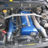
IMO: if you really want to keep the VQ, supercharge it. Otherwise, VR38DETT/VR30DETT conversion, or sell for a better base car. Or go wild with a V8 turbo conversion, or a Hartley V12...
-
-
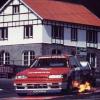
No shit I've fixed shudder/noise by slamming on the brakes a couple of times from 60-80 km/h. If they still made noise after that, take the pads out, rub on concrete floor/file the friction surface, install and bed in. Fixed like 3x QFM pads for me. Oh and if you're tracking it, never skimp out. You may recall my R31 at Oran Park many years ago with melted pads...
-


Recommended Posts
Create an account or sign in to comment
You need to be a member in order to leave a comment
Create an account
Sign up for a new account in our community. It's easy!
Register a new accountSign in
Already have an account? Sign in here.
Sign In Now