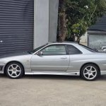
Jump to content
SAU Community

Recommended Posts

  • Replies 128
  • Created
  • Last Reply

Top Posters In This Topic

Top Posters In This Topic

Posted Images

I plan for it to be an all round car, street, drift, drags, track, and shows.

I've had the car only 12 months, mite take a couple of years but thats the intension to build an all rounder.

I have coil overs and wheels comming next month.

The car is currently sitting in the workshop , im completing the next series of modifications.

  • 1 month later...

Bit of a decent update,

Im going to include alot more pics this time just to give you guys an idea on how much work goes into getting things perfect. So much work goes into aftermarket products to make them fit like oem products.

Heres a few pics of my cf boot, the carbon has been laid perfect but the underside moulding was terribly out of shape cause the boot to fit okay but nowhere near the standard I want to achieve for this car. So i had to cut and remove the shape out of the boot and remould it to fit perfect, this took hours and hours of work to get right. What I ended up with is a perfect fitting cf boot which is really hard to get.

Reshaping of the boot, this was only the first stage I didnt get pics of the next stage.

nov3.jpg

Filled and primed

nov1.jpg

Finish coat, still had a few coats to go but you get the idea.

nov.jpg

Boot completed.

Okay heres a bunch of pics where I am up to atm including the new front bar. Gives you guys an idea why I chose the black over the orange! Please feel free to comment

dec1.jpg

dec2.jpg

dec3.jpg

dec4.jpg

dec5.jpg

dec6.jpg

dec7.jpg

dec8.jpg

Just a tip i found with taking pics of my car in sunlight; as your car also seems to have a pearl.

With my camera i have to press the button half way to focus, then continue pressing it to take the photo. If yours is the same, try to focus on something lighter (whiter) that is roughly the same distance from your car, then turn the lens to your car to take the photo. I found that the pearl "fools" the camera and the pic ends up over exposed.

Just to show you an example, i've added two pics of photos of my car.

This first i focused on my car, you can see the shot is totally over exposed. Have a look at the white 33 in the left corner, and the sandy gravel.

post-1811-1167219306.jpg

This second pic i focused on the white car, and i prefer to see my paint colour in this type of shade.

post-1811-1167219333.jpg

Create an account or sign in to comment

You need to be a member in order to leave a comment

Create an account

Sign up for a new account in our community. It's easy!

Register a new account

Sign in

Already have an account? Sign in here.

Sign In Now


  • Similar Content

  • Latest Posts

    • For once a good news  It needed to be adjusted by that one nut and it is ok  At least something was easy But thank you very much for help. But a small issue is now(gearbox) that when the car is stationary you can hear "clinking" from gearbox so some of the bearing is 100% not that happy... It goes away once you push clutch so it is 100% gearbox. Just if you know...what that bearing could be? It sounding like "spun bearing" but it is louder.
    • Yeah, that's fine**. But the numbers you came up with are just wrong. Try it for yourself. Put in any voltage from the possible range and see what result you get. You get nonsense. ** When I say "fine", I mean, it's still shit. The very simple linear formula (slope & intercept) is shit for a sensor with a non-linear response. This is the curve, from your data above. Look at the CURVE! It's only really linear between about 30 and 90 °C. And if you used only that range to define a curve, it would be great. But you would go more and more wrong as you went to higher temps. And that is why the slope & intercept found when you use 50 and 150 as the end points is so bad halfway between those points. The real curve is a long way below the linear curve which just zips straight between the end points, like this one. You could probably use the same slope and a lower intercept, to move that straight line down, and spread the error out. But you would 5-10°C off in a lot of places. You'd need to say what temperature range you really wanted to be most right - say, 100 to 130, and plop the line closest to teh real curve in that region, which would make it quite wrong down at the lower temperatures. Let me just say that HPTuners are not being realistic in only allowing for a simple linear curve. 
    • I feel I should re-iterate. The above picture is the only option available in the software and the blurb from HP Tuners I quoted earlier is the only way to add data to it and that's the description they offer as to how to figure it out. The only fields available is the blank box after (Input/ ) and the box right before = Output. Those are the only numbers that can be entered.
    • No, your formula is arse backwards. Mine is totally different to yours, and is the one I said was bang on at 50 and 150. I'll put your data into Excel (actually it already is, chart it and fit a linear fit to it, aiming to make it evenly wrong across the whole span. But not now. Other things to do first.
    • God damnit. The only option I actually have in the software is the one that is screenshotted. I am glad that I at least got it right... for those two points. Would it actually change anything if I chose/used 80C and 120C as the two points instead? My brain wants to imagine the formula put into HPtuners would be the same equation, otherwise none of this makes sense to me, unless: 1) The formula you put into VCM Scanner/HPTuners is always linear 2) The two points/input pairs are only arbitrary to choose (as the documentation implies) IF the actual scaling of the sensor is linear. then 3) If the scaling is not linear, the two points you choose matter a great deal, because the formula will draw a line between those two points only.
×
×
  • Create New...