Jump to content
SAU Community

Recommended Posts

  • Replies 40
  • Created
  • Last Reply

Top Posters In This Topic

Top Posters In This Topic

Posted Images

Yesterday i went out and i couldnt find that thermofoam anywhere.I went to rocket and bought some stuff called thermo-mat.Its foil on both sides with what looks like fibreglass matting in the middle.Cost me $50 for a 120cm square sheet of it.Anyway i measured it up,cut it out and put it in the CAI.Havent really driven it much since then but surely it would do something.

How did it go ducting the air in from the side? Do you know how the guy that did that find it? Where would the CAI hose run if I did this?

I would prefer to use the stock intercooler holes, but I have the Blitz kit which uses them, and I don't have a stock snorkel.

sorry to be a wet sock, but, that is still going to draw heat in from the headlight at night, is it not?

Im in the process of trying to "think" up a completely "sealed" design, with only one air intake through the base to use the stock intercooler piping hole as a cold air intake point. Will be fabbing it up at work (work at a sheetmetal place :dry:). Will be a bastard of a job i think =[

Compared with engine bay temps, I think the heat from the BACK of the headlight would be negligible. Remember that one day you will probably have to change a headlight bulb so make sure if you put somethign behind it that it is easy to remove. If you are that worried about it I would just tuck some foam in behind the headlight and secure it at the corners.

Hi mate,

Where abouts did you get the ALUCOBOND (im in tassie 2)

cheers

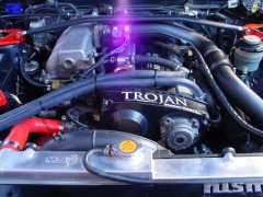
Well so i was sitting on the net, going over all the CAI designs, ones you can buy and so forth. I remebered that a member of the forum had some templates. SO got those and went to work.

My dad and I started in the morning on boxing day, figured we would take it easy, well 4 hours later, and a six pack of beer, and HAY PRESTO, here is the finished result.

The box case is made out of a product called ALUCOBOND, it's a 1mm ally, with 3mm PVC, and 1 mm ally again. You can buy a thicker ones if required. The inside is lined wiht a THERMOFOAM, it's a 15mm thinck high density foam with silver foil, excellent R values, to miniminse heat transfer. I noticed a 6deg C after introducing the foam.

The air is introduced through a 2'5" pipe from the front of the bar and blows straigh into the box.

SO far the results are great, the car is a lot more constant, if you stand in trafic, the heat lag is gone. The air is nice and cool, and the car is a lot more responsive. Fuel ecconomy is up, and the pod noise is reduced to a more acceptable level.

Only down side, on a cold morning, the dam thing hits R&R so dam quick, as the air is so dense, and the box together with the FMIC, really increase the air flow, hence R&R.

I have the templates available, if people are interested, but i modified mine as i went allong, i found that each car is different. I have done this to my friends R33 4door, with an APEXI filter, and we had to extend the main box body and make a different cover top.

I did mine by making the side first and then making up a pattern to fit for the top cover. The side of the box is held in place by two brackets riveted to the side of the box, and bolted to the car using the stock airbox mounting holes. The top is slid inot place under the front panel, and then bolted through the top, into some brass L-brackets. I then finished the alluminium by brushing it with fine still wool. I did have it polished, but it was VERY hard to keep semi clean. Total cost, ALUCABOND, free i got offcuts, Thermofoam $36 per meter, and all the other bits and peices i already had, so that is DAM Cheep.

Tell us what you think.

woolls, i'll get some on monday, you can only get it form TasCon on argyle street and i know the guy so i can get it for free, or you can go in and for a carton of beer you can have as much as you want. offcuts ofcourse. PM me and we'll chat

Compared with engine bay temps, I think the heat from the BACK of the headlight would be negligible. Remember that one day you will probably have to change a headlight bulb so make sure if you put somethign behind it that it is easy to remove. If you are that worried about it I would just tuck some foam in behind the headlight and secure it at the corners.

Any tiny bit of heat you can get rid of can help, the colder the better :)

Either the foam or just a detachable/screw in section.

Any tiny bit of heat you can get rid of can help, the colder the better :laugh:

Either the foam or just a detachable/screw in section.

Even with the thermo foam etc in place you would still get a lot more heat coming through the shield than you would get from the headlights,

If you do decide to shield from the headlight please post results. I would guess there would be no noticable difference.

the amount of heat of the headlights would be sweet F.A. the rear of the light is plastic, which doesn't conduct heat well. if you put you hand over the back of the light it will only be slightly warm.

you would get more heat radiating off the intercooler pipe that runs from the turbo to the cooler.

as for making a completely sealed box, i'm undecided on this. sure you wouldn't get any hot air coming in, but if you don't have a big enough feed at high rpm it may end up being a restriction. if you don't have it set up right at WOT at high rpm you might be only getting 90% of the air that could be used. if it isn't fully sealed in the same situation it will be able to get 100% air. and the small amount of warm air is going to be better than not enough air.

Agreeing with MAD082 that plastic is a bad conductor of heat, that’s why I decided to make my CAI box out of acrylic. As most stock CAI boxes are made of a plastic which must have some purpose or reason. Otherwise wouldn’t all major car manufacturers make them out of some other material?

looks great mate...well done.

as for heat from the lights...lol it would contribute sweet FA and only be an issue when the lights we ON...

not withstanding...the amount of air comming in and the heat it would disipate through the plastic backing would amount to FA.

Create an account or sign in to comment

You need to be a member in order to leave a comment

Create an account

Sign up for a new account in our community. It's easy!

Register a new account

Sign in

Already have an account? Sign in here.

Sign In Now


  • Similar Content

  • Latest Posts

    • Thought I would get some advice from others on this situation.    Relevant info: R33 GTS25t Link G4x ECU Walbro 255LPH w/ OEM FP Relay (No relay mod) Scenario: I accidentally messed up my old AVS S5 (rev.1) at the start of the year and the cars been immobilised. Also the siren BBU has completely failed; so I decided to upgrade it.  I got a newer AVS S5 (rev.2?) installed on Friday. The guy removed the old one and its immobilisers. Tried to start it; the car cranks but doesnt start.  The new one was installed and all the alarm functions seem to be working as they should; still wouldn't start Went to bed; got up on Friday morning and decided to have a look into the no start problem. Found the car completely dead.  Charged the battery; plugged it back in and found the brake lights were stuck on.  Unplugging the brake pedal switch the lights turn off. Plug it back in and theyre stuck on again. I tested the switch (continuity test and resistance); all looks good (0-1kohm).  On talking to AVS; found its because of the rubber stopper on the brake pedal; sure enough the middle of it is missing so have ordered a new one. One of those wear items; which was confusing what was going on However when I try unplugging the STOP Light fuses (under the dash and under the hood) the brake light still stays on. Should those fuses not cut the brake light circuit?  I then checked the ECU; FP Speed Error.  Testing the pump again; I can hear the relay clicking every time I switch it to ON. I unplugged the pump and put the multimeter across the plug. No continuity; im seeing 0.6V (ECU signal?) and when it switches the relay I think its like 20mA or 200mA). Not seeing 12.4V / 7-9A. As far as I know; the Fuel Pump was wired through one of the immobiliser relays on the old alarm.  He pulled some thick gauged harness out with the old alarm wiring; which looks to me like it was to bridge connections into the immobilisers? Before it got immobilised it was running just fine.  Im at a loss to why the FP is getting no voltage; I thought maybe the FP was faulty (even though I havent even done 50km on the new pump) but no voltage at the harness plug.  Questions: Could it be he didnt reconnect the fuel pump when testing it after the old alarm removal (before installing the new alarm)?  Is this a case of bridging to the brake lights instead of the fuel pump circuit? It's a bit beyond me as I dont do a lot with electrical; so have tried my best to diagnose what I think seems to make sense.  Seeking advice if theres for sure an issue with the alarm install to get him back here; or if I do infact, need an auto electrician to diagnose it. 
    • Then, shorten them by 1cm, drop the car back down and have a visual look (or even better, use a spirit level across the wheel to see if you have less camber than before. You still want something like 1.5 for road use. Alternatively, if you have adjustable rear ride height (I assume you do if you have extreme camber wear), raise the suspension back to standard height until you can get it all aligned properly. Finally, keep in mind that wear on the inside of the tyre can be for incorrect toe, not just camber
    • I know I have to get a wheel alignment but until then I just need to bring the rear tyres in a bit they're wearing to the belt on the inside and brand new on the outside edge. I did shorten the arms a bit but got it wrong now after a few klms the Slip and VDC lights come on. I'd just like to get it to a point where I can drive for another week or two before getting an alignment. I've had to pay a lot of other stuff recently so doing it myself is my only option 
    • You just need a wheel alignment after, so just set them to the same as current and drive to the shop. As there are 2 upper links it may also be worth adding adjustable upper front links at the same time; these reduce bump steer when you move the camber (note that setting those correctly takes a lot longer as you have to recheck the camber at each length of the toe arm, through a range of movement, so you could just ignore that unless the handling becomes unpredictable)
    • I got adjustable after market rear camber arm to replace the stock one's because got sick of having to buy new rear tyres every few months. Can anyone please let me know what the best adjustment length would be. I don't have the old ones anymore to get measurements. I'm guessing the stock measurement minus a few mm would do it. Please any help on replacing them would be fantastic I've watched the YouTube clips but no-one talks about how long to set the camber arm to.
×
×
  • Create New...