Jump to content
SAU Community

Recommended Posts

very keen to see what you think of the FET ones. they are black right? with a little red bit on the top? i've seen a few saurus cars in japan using them.

very keen to see what you think of the FET ones. they are black right? with a little red bit on the top? i've seen a few saurus cars in japan using them.

all red, but mine are quite old the newer ones may be differrent. I will check.

very keen to see what you think of the FET ones. they are black right? with a little red bit on the top? i've seen a few saurus cars in japan using them.

They are all red

There is another company making similar coils called Okaka Projects, not sure what colour they use.

all red, but mine are quite old the newer ones may be differrent. I will check.

hmm, that could be them. i am running the splitfires now (and they have been fine to this point), but I can't help but feel there is a better option. I notice some very hardcore cars built by saurus running what I think are the FET ones, and I noticed when I was at veilside their R32 GTR drag car was running standard coils... I was so shocked I even asked Hiranao to make sure. as at the time it went against my belief that standard = crap. I now seem to lean towards: worn out standard = crap, but brand new nissan coils = the best (but cost is way too much).

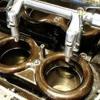
http://cgi.ebay.com.au/FET-DIRECT-IGNITION...8QQcmdZViewItem

found these for sale on ebay ^^^^ they are the same as the ones i have.

post-34927-1178178154.jpg

Edited by URAS

I always worried about editing this feature in the PFC because I believe Datalogit have their description incorrect. How can coil dwell be dependant upon rpm? Secondary coil voltage is dependant upon input power so with a fixed impeadance only voltage and dwell will affect the final spark engergy. Most of the jap stuff I have seen - including tuning of factory ECU's, coil dwell is allways based upon amount dwell vs battery voltage not rpm unless of course its duty clyle based - but then the numbers dont make sense.

Has anybody had time to scope the dwell after editing this table? And yes there is a point that more dwell will result in less secondary coil voltage.

Maybe the thinking behind this is that if you give the coil enought dwell to produce maximum spark energy all the time, then they will overheat, so i guess you could give it a bit more dwell around peak BMEP/torque, to give it the added spark energy without the fear of cooking the coils, as they aren't getting that dwell much of the time? I remember reading that splitfires like a bit more dwell than standard, so i believe it is possible that they may have a different gauge wiring, combined with a different winding ratio between the primary and secondary circuits, food for thought..., please feel free to diagree

I hear what your saying but spark energy is "usually" a function of dwell vs batery voltage not dwell vs rpm - as it is within the datalogit software. Dont get me wrong this table may affect dwell but it may just be worded incorrectly and the scaling from hexidecimal to actual engineering numbers may be wrong. Its one of those things I would test if I only had a free second at work!!!

why are these settings sweet?

what are the benefits of these settings?

Are these going to be best for all cars? if not which ones?

as there isnt much point for posting it if there isnt anything for everyone on the forums besides tuners

Ther was a thread on here a while ago about increasing the dwell on PFC to 1.7ms to suit the splitfires, is it only from the datalogit, or can it be done from the h/c(its been ages since i used one.)I would have thought dwell vs batt voltage would be a no brainer, batt voltage down a little, give it a bit more dwell. If this works as rob says and isnt just a bad translation, i dont see why everyone couldnt tailor their dwell to suit their application, could even set the PFC up to run external bosch coils if the range is big enough(how high can it go?)

Edited by Adriano
I hear what your saying but spark energy is "usually" a function of dwell vs batery voltage not dwell vs rpm - as it is within the datalogit software. Dont get me wrong this table may affect dwell but it may just be worded incorrectly and the scaling from hexidecimal to actual engineering numbers may be wrong. Its one of those things I would test if I only had a free second at work!!!

There is almost always two settings;

IGNITION VOLTAGE DWELL COMPENSATION (amount of time added to base ignition dwell as a function of ignition voltage)

IGNITION DWELL PERIOD ((length of time the ignition coil dwells as a function of rpm) sometimes this is a percentage of duty, like remaps for example)

My thinking is that there is a scaler of "base dwell time" that is not accessable via datalogit or the hand controller. Then there is a mutiplier "IGN vs BatV" which should read "Ignition Dwell mutiplier vs BatV". Then the "IGN dwell vs RPM" is another mutilpier based on RPM.

Also it cant be duty cycle based as all nissan's use dumb ignitors.

Create an account or sign in to comment

You need to be a member in order to leave a comment

Create an account

Sign up for a new account in our community. It's easy!

Register a new account

Sign in

Already have an account? Sign in here.

Sign In Now


  • Similar Content

  • Latest Posts

    • My apologies. I forgot we were talking about weird beard M series stuff. Had been talking elsewhere with someone about an R33 with similar subject and got confused.
    • Nope, I don't like the look of ND RF, or any ND really, I don't like their faces or arses, why, because of their "modern" lines, the NC, whilst "modernish" has a more rounded shape that I like Well, that's how my overly judgemental eyes see it anyway  
    • Should be more than fine, especially the overall fuel pressure would never exceed 3.5bar (assuming that thing never gets more than 0.5bar of boost in stock form). According to the chart, it's 11amps.
    • I definitely know the first rule here, look first, ask second. I've seen many people get roasted 😂 I found a few diagrams for the RB, but I'm yet to come across one for the VQ. From what I have read, the pump gets the +12v along with the FPCM, and it's the negative wire that gets passed through the resistor to regulate the voltage. So I assume I can just ground the negative wire at the pump to eliminate the FPCM control. But I really wanted to see the VQ circuit diagram first to make sure I understood it correctly. Once the new pump is in I'll do some testing to see how it behaves, and in the meantime, I'll keep looking for a wiring diagram. Thanks for your help mate, your time is greatly appreciated.    
    • Maybe? I have the Supercheap ToolPro low thingo. It has a somewhat smaller diameter lifting "bowl" than you would expect on a workshop grade trolley jack, and a split rubber pad to suit that diameter. It clears the "N1" style skirts I have. Probably wouldn't if the jack's bowl and a suitably larger rubber block were in use. Having said that though.....you only need the rubber block to exist on the inner side of the pinchweld, so could carve away any rubber that fouled the skirt, leaving some there for "insurance" </simples>
×
×
  • Create New...