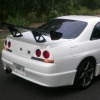
Jump to content
SAU Community

Recommended Posts

I bought this car to use build up as a drift car but have not really got the time and hae decided to move on.

details:

White 1992 R32 GTST Mspec.

has a new front bar and a pair of mspec sideskirts and a rear wing. the body is in good condition and there is no dents. the paint is ok and will come up pretty well in most places but it has a few chips ect. the car is missing a few minor parts. off the top of my head they are: climate control box, rear pillar trims, dash vents, rear screen trim, possibly wipers and some other bits and peices. the bonnet is gunmetal and has a few dints. it could easily be repaired and painted. it is missing the blowoff valve and a few really minor engine hoses. it has 4 piston callipers and stock wheels with tyres in good condition. the car is Auto and I have a manual tailshaft and some other bits to do a manual conversion. I was going to go to pick a part and get an R31 bot for $150 and put that in for some cheap manual action.

it HAS been complied and was registered in victoria untill the rego lapsed. it has no defects and is not written off and has not been reported as stolen. it will need a bit of work to get it roadworthy but is mechanically very good. the suspension, brakes, steering and engine are all in good condition.

as I said I was going to buld it up as a drift car but dont really have the time or room to do it now. if you did a bit of work and spent a few bucks you would have a car worth 8 to 10g.

I have replaced the coilpacks, engine loom replaced a headlight and some other bits and pices. since I have had it

The car also comes with a full TRUST exhaust, full alarm/immobiliser with central locking, and a pair of JIC coilovers.

the car is located in Melbourne but i am happy to freight it to you if you are keen. and it might work out well if you are after a cheap skyline. It drives and runs fine but has major boost leaks as its missing some hoses so you COULD pick it up and drive away but prob better to tow it.

I will organise photos soon but I am guessing at the price its not going to be here long so give me a buzz quick if you are interested.

Cheers!

Nic 0435145987

Link to comment
https://www.sau.com.au/forums/topic/259259-r32-skyline-gtst-white-mspec-3500/
Share on other sites

Create an account or sign in to comment

You need to be a member in order to leave a comment

Create an account

Sign up for a new account in our community. It's easy!

Register a new account

Sign in

Already have an account? Sign in here.

Sign In Now


  • Similar Content

  • Latest Posts

    • Nah, that is hella wrong. If I do a simple linear between 150°C (0.407v) and 50°C (2.98v) I get the formula Temperature = -38.8651*voltage + 165.8181 It is perfectly correct at 50 and 150, but it is as much as 20° out in the region of 110°C, because the actual data is significantly non-linear there. It is no more than 4° out down at the lowest temperatures, but is is seriously shit almost everywhere. I cannot believe that the instruction is to do a 2 point linear fit. I would say the method I used previously would have to be better.
    • When I said "wiring diagram", I meant the car's wiring diagram. You need to understand how and when 12V appears on certain wires/terminals, when 0V is allowed to appear on certain wires/terminals (which is the difference between supply side switching, and earth side switching), for the way that the car is supposed to work without the immobiliser. Then you start looking for those voltages in the appropriate places at the appropriate times (ie, relay terminals, ECU terminals, fuel pump terminals, at different ignition switch positions, and at times such as "immediately after switching to ON" and "say, 5-10s after switching to ON". You will find that you are not getting what you need when and where you need it, and because you understand what you need and when, from working through the wiring diagram, you can then likely work out why you're not getting it. And that will lead you to the mess that has been made of the associated wires around the immobiliser. But seriously, there is no way that we will be able to find or lead you to the fault from here. You will have to do it at the car, because it will be something f**ked up, and there are a near infinite number of ways for it to be f**ked up. The wiring diagram will give you wire colours and pin numbers and so you can do continuity testing and voltage/time probing and start to work out what is right and what is wrong. I can only close my eyes and imagine a rat's nest of wiring under the dash. You can actually see and touch it.
    • So I found this: https://www.efihardware.com/temperature-sensor-voltage-calculator I didn't know what the pullup resistor is. So I thought if I used my table of known values I could estimate it by putting a value into the pullup resistor, and this should line up with the voltages I had measured. Eventually I got this table out of it by using 210ohms as the pullup resistor. 180C 0.232V - Predicted 175C 0.254V - Predicted 170C 0.278V - Predicted 165C 0.305V - Predicted 160C 0.336V - Predicted 155C 0.369V - Predicted 150C 0.407V - Predicted 145C 0.448V - Predicted 140C 0.494V - Predicted 135C 0.545V - Predicted 130C 0.603V - Predicted 125C 0.668V - Predicted 120C 0.740V - Predicted 115C 0.817V - Predicted 110C 0.914V - Predicted 105C 1.023V - Predicted 100C 1.15V 90C 1.42V - Predicted 85C 1.59V 80C 1.74V 75C 1.94V 70C 2.10V 65C 2.33V 60C 2.56V 58C 2.68V 57C 2.70V 56C 2.74V 55C 2.78V 54C 2.80V 50C 2.98V 49C 3.06V 47C 3.18V 45C 3.23V 43C 3.36V 40C 3.51V 37C 3.67V 35C 3.75V 30C 4.00V As before, the formula in HPTuners is here: https://www.hptuners.com/documentation/files/VCM-Scanner/Content/vcm_scanner/defining_a_transform.htm?Highlight=defining a transform Specifically: In my case I used 50C and 150C, given the sensor is supposedly for that. Input 1 = 2.98V Output 1 = 50C Input 2 = 0.407V Output 2 = 150C (0.407-2.98) / (150-50) -2.573/100 = -0.02573 2.98/-0.02573 + 47.045 = 50 So the corresponding formula should be: (Input / -0.02573) + 47.045 = Output.   If someone can confirm my math it'd be great. Supposedly you can pick any two pairs of the data to make this formula.
    • Well this shows me the fuel pump relay is inside the base of the drivers A Pillar, and goes into the main power wire, and it connects to the ignition. The alarm is.... in the base of the drivers A Pillar. The issue is that I'm not getting 12v to the pump at ignition which tells me that relay isn't being triggered. AVS told me the immobiliser should be open until the ignition is active. So once ignition is active, the immobiliser relay should be telling that fuel pump relay to close which completes the circuit. But I'm not getting voltage at the relay in the rear triggered by the ECU, which leaves me back at the same assumption that that relay was never connected into the immobiliser. This is what I'm trying to verify, that my assumption is the most likely scenario and I'll go back to the alarm tech yet again that he needs to fix his work.      Here is the alarms wiring diagram, so my assumption is IM3A, IM3B, or both, aren't connected or improper. But this is all sealed up, with black wiring, and loomed  
×
×
  • Create New...