Jump to content
SAU Community

Recommended Posts

have you thought about running the external gate from the exhaust housing? i done that with my turbo and $250 50mm gate and its perfect. holds whatever boost i set it at with no creep at all

unfortunatly not adriano, just 1 side. hence different back pressure against front 3 from back 3. I was going to run a spacer between the manifold and the turbo with a gate on it but i do not have enough room.

and I would rather bugger a manifold worth $40 than a turbine housing. also if i have to i can easily enough swap over the manifoldback to a non gated one if i have to.

some have mentioned the possinility of tapping a thread in the manifold and screwing a 50mm pipe in the thread that the gate comes off. this looks like a good ideal as welding cast iron is a bit of a hit and miss operation. I have a mig but my skills are not very good yet and i would most likely crack the mani even if i preheated it.

I am going to install the gate on the manifold so it feeds off both sides of the seperator. i really dont need it to come on boost earlier :D i like the way it comes on now.

can you explain a bit? where would the gate go? and what wouuld ot feed from Cheers"

I thought about doing that but the plumbing would be above what i can do due to the cast welding.

so i am going to stick with the manifold gate :D

results in 2 weeks poeple!

UPDATE:

My replacement stock manifold arrived and so did the new wastegate. I bought 2 90deg long radius steampipe bends from reece plumbing.

The manifold has been drilled on both sides of the devider and I have cut 2 elongated ports and filed them smooth but leaving the devider intact. the steam pipe was then cu to suit the profile of the manifold and tacked in place the 2nd elbow was welded to the first in the right orentation and the gate flange welded to it.

I then welded the new gate pipe to the manifold. I was going to get it done professionally but decided to attempt it myself as i really wanted it finished thes weekend. I cleaned the manifold and gate pipe with a wire brush and used flux core gasless wire to weld it as the flux apparently helps bind the mild steel and cast iron. I fed quite a bit of heat into it and used 130amps and kept a HUGE weld pool. did it in 3 passes and it looks fairly strong. will wait and see once it has cooled down :domokun:

so the manifold is now done and will go back on the car tomorrow after it is cleaned up and painted...

well so much for stock looking car :/ I was really hoping to get away with the internal gate but the external was always going to be the better option.

Manifold is now on! the external gate sounds evil :thumbsup: looks like it holds boost very well. the 12psi spring seems to hold boost just fine just using the side port and leaving the top port to vent to atmosphere.

photos will be coming later tonight!

cheers!

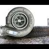
P1000211.jpg

P1000212.jpg

P1000215.jpg

once i have had a chance to to a nice WOT in 4th and i am satisfied it holds boost flat it will be a trip back to the dyno and finally some results. I will try and book some time this following week if i can. probably needs about 2 hours more tuning.

the ghetto boost line will be fixed. i just ran out of hose and used what i had laying around, it will run from the plenum across the back of the firewall to the gate. I still dont have the screamer plumbed into the exhaust. i am going to get some 1&1/2" mandrel bends to do it properly but i think i will drive it around like this for a while to frighten small children :P

Adriano,

I looked at it for ges and no, the manifold would be hacked to buggery to do it. I really wanted to do it that way but nevermind :P

CJ, Will do! I will mount the camera and go for a drive over the next couple of days!

  • 2 weeks later...
Adriano,

I looked at it for ges and no, the manifold would be hacked to buggery to do it. I really wanted to do it that way but nevermind ;)

CJ, Will do! I will mount the camera and go for a drive over the next couple of days!

where are these videos.. Im also using a hx40w, 16cm2 exhasut side on my l28, Also convinced my mate and found him another hx40 16cm2 for his rb25det.. :happy:

yeha I will get there :P

too much on the go at the moment, I have jsut finished rebuilding a CBR600R and now have to cafe racers is bits in my garage. it never ends, i have kind of given the car a break for now but will finish this soon,

The car is on the road and daily driven at the moment when the gate opens it breaks traction HARD! its pretty loud!

has anyone else got any figures from these turbos on RB's yet?

Sorry, we have a typhoon here right now so no vids for the next couple of days. Soon though, I promise. I've got a couple other people asking for them on another board also, so I'll get to it soon.

CEF, what kind of figures are you looking for? HP/dyno/track numbers I assume? Best place for that would be the results thread the DSM guys have put together here but those are mostly 2.0L 4G63 motors, so it's not apples to apples.

Would be good to see some actual dyno figures for a Holset on an RB, as much fun as it all sounds any semi-decent reasonable sized turbo makes for a fun drive on an RB25 :P

Would be good to see some actual dyno figures for a Holset on an RB, as much fun as it all sounds any semi-decent reasonable sized turbo makes for a fun drive on an RB25 :)

fingers crossed we'll find out soon with nish's car

Create an account or sign in to comment

You need to be a member in order to leave a comment

Create an account

Sign up for a new account in our community. It's easy!

Register a new account

Sign in

Already have an account? Sign in here.

Sign In Now


  • Latest Posts

    • Wheel alignment immediately. Not "when I get around to it". And further to what Duncan said - you cannot just put camber arms on and shorten them. You will introduce bump steer far in excess of what the car had with stock arms. You need adjustable tension arms and they need to be shortened also. The simplest approach is to shorten them the same % as the stock ones. This will not be correct or optimal, but it will be better than any other guess. The correct way to set the lengths of both arms is to use a properly built/set up bump steer gauge and trial and error the adjustments until you hit the camber you need and want and have minimum bump steer in the range of motion that the wheel is expected to travel. And what Duncan said about toe is also very true. And you cannot change the camber arm without also affecting toe. So when you have adjustable arms on the back of a Skyline, the car either needs to go to a talented wheel aligner (not your local tyre shop dropout), or you need to be able to do this stuff yourself at home. Guess which approach I have taken? I have built my own gear for camber, toe and bump steer measurement and I do all this on the flattest bit of concrete I have, with some shims under the tyres on one side to level the car.
    • Thought I would get some advice from others on this situation.    Relevant info: R33 GTS25t Link G4x ECU Walbro 255LPH w/ OEM FP Relay (No relay mod) Scenario: I accidentally messed up my old AVS S5 (rev.1) at the start of the year and the cars been immobilised. Also the siren BBU has completely failed; so I decided to upgrade it.  I got a newer AVS S5 (rev.2?) installed on Friday. The guy removed the old one and its immobilisers. Tried to start it; the car cranks but doesnt start.  The new one was installed and all the alarm functions seem to be working as they should; still wouldn't start Went to bed; got up on Friday morning and decided to have a look into the no start problem. Found the car completely dead.  Charged the battery; plugged it back in and found the brake lights were stuck on.  Unplugging the brake pedal switch the lights turn off. Plug it back in and theyre stuck on again. I tested the switch (continuity test and resistance); all looks good (0-1kohm).  On talking to AVS; found its because of the rubber stopper on the brake pedal; sure enough the middle of it is missing so have ordered a new one. One of those wear items; which was confusing what was going on However when I try unplugging the STOP Light fuses (under the dash and under the hood) the brake light still stays on. Should those fuses not cut the brake light circuit?  I then checked the ECU; FP Speed Error.  Testing the pump again; I can hear the relay clicking every time I switch it to ON. I unplugged the pump and put the multimeter across the plug. No continuity; im seeing 0.6V (ECU signal?) and when it switches the relay I think its like 20mA or 200mA). Not seeing 12.4V / 7-9A. As far as I know; the Fuel Pump was wired through one of the immobiliser relays on the old alarm.  He pulled some thick gauged harness out with the old alarm wiring; which looks to me like it was to bridge connections into the immobilisers? Before it got immobilised it was running just fine.  Im at a loss to why the FP is getting no voltage; I thought maybe the FP was faulty (even though I havent even done 50km on the new pump) but no voltage at the harness plug.  Questions: Could it be he didnt reconnect the fuel pump when testing it after the old alarm removal (before installing the new alarm)?  Is this a case of bridging to the brake lights instead of the fuel pump circuit? It's a bit beyond me as I dont do a lot with electrical; so have tried my best to diagnose what I think seems to make sense.  Seeking advice if theres for sure an issue with the alarm install to get him back here; or if I do infact, need an auto electrician to diagnose it. 
    • Then, shorten them by 1cm, drop the car back down and have a visual look (or even better, use a spirit level across the wheel to see if you have less camber than before. You still want something like 1.5 for road use. Alternatively, if you have adjustable rear ride height (I assume you do if you have extreme camber wear), raise the suspension back to standard height until you can get it all aligned properly. Finally, keep in mind that wear on the inside of the tyre can be for incorrect toe, not just camber
    • I know I have to get a wheel alignment but until then I just need to bring the rear tyres in a bit they're wearing to the belt on the inside and brand new on the outside edge. I did shorten the arms a bit but got it wrong now after a few klms the Slip and VDC lights come on. I'd just like to get it to a point where I can drive for another week or two before getting an alignment. I've had to pay a lot of other stuff recently so doing it myself is my only option 
    • You just need a wheel alignment after, so just set them to the same as current and drive to the shop. As there are 2 upper links it may also be worth adding adjustable upper front links at the same time; these reduce bump steer when you move the camber (note that setting those correctly takes a lot longer as you have to recheck the camber at each length of the toe arm, through a range of movement, so you could just ignore that unless the handling becomes unpredictable)
×
×
  • Create New...